background image

23

Troubleshooting

Adjustments & Service

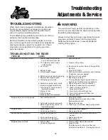
TROUBLESHOOTING

While normal care and regular maintenance will extend
the life of your equipment, prolonged or constant use
may eventually require that service be performed to
allow it to continue operating properly.

The troubleshooting guide below lists the most common
problems, their causes and remedies.

See the information on the following pages for instruc-
tions on how to perform most of these minor adjustments
and service repairs yourself. If you prefer, all of these
procedures can be performed for you by your local
authorized dealer.

WARNING

To avoid serious injury, perform maintenance on the
tractor or mower only when the engine is stopped and
the parking brake engaged. 

Always remove the ignition key, disconnect the spark
plug wire and fasten it away from the plug before
beginning the maintenance, to prevent accidental
starting of the engine.

TROUBLESHOOTING THE RIDER

PROBLEM

CAUSE

REMEDY

Engine will not turnover or start.

1. Ground speed control lever

1. Shift into neutral.

not in neutral-start position.

2. PTO (electric clutch) switch 

2. Place in OFF position.

in ON position.

3. Out of fuel.

3. If engine is hot, allow it to cool, then refill the 

fuel tank.

4. Engine flooded.

4. Open the CHOKE.

5. Circuit breaker tripped. 

5. Wait one minute for automatic reset. Replace 

if defective (see your dealer).

6. Battery terminals require cleaning.

6. See Normal Care section.

7. Battery discharged or dead.

7. Recharge or replace.

8. Wiring loose or broken. 

8. Visually check wiring & replace broken or 

frayed wires. Tighten loose connections.

9. Solenoid or starter motor faulty.

9. Repair or replace. (see your dealer.)

10. Safety interlock switch faulty. 

10. Replace if needed (see your dealer.)

11. Spark plug(s) faulty, fouled or 

11. Clean and gap or replace.

incorrectly gapped. 

See engine manual.

12. Water in fuel. 

12. Drain fuel & refill with fresh fuel.

13. Old stale gas. 

13. Drain fuel & replace with fresh fuel.

14. Brake pedal not depressed.

14. Depress pedal.

Engine starts hard or runs poorly.

1. Fuel mixture too rich. 

1. Open the CHOKE.

If problem persists, clean the air filter.  
(See engine manual.)

2. Carburetor adjusted incorrectly.

2. See engine manual.

3. Spark plug(s) faulty, fouled, or 

3. Clean & gap or replace. See engine manual.

incorrectly gapped.

Engine knocks.

1. Low oil level.

1. Check/add oil as required.

2. Using wrong grade oil.

2. See engine manual.

Excessive oil consumption.

1. Engine running too hot.

1. Clean engine fins, blower screen and air 

cleaner.

2. Using wrong weight oil.

2. See engine manual.

3. Too much oil in crankcase.

3. Drain excess oil.

Engine exhaust is black.

1. Dirty air filter.

1. Clean air filter. See engine manual.

2. Choke not fully open.

2. Open CHOKE.

If problem persists, check air filter and 
carburetor adjustments.  See engine manual.

Summary of Contents for 2400 Series

Page 1: ...ption 2690648 Coronet 13HP 30 Mower CE 2690650 2413H 13HP 30 Mower CE 2690649 RT1330 13HP 30 Mower CE 30 Mower Decks Mfg No Description 1694511 30 Mower Deck CE 1694537 30 Mower Deck CE 1694515 30 Mower Deck CE 1734067 Revision No 00 Rev Date 11 2006 TP 100 4436 00 CO SMAN ...

Page 2: ......

Page 3: ...7 Safety Decals 8 Features Controls 10 Control Functions 10 Safety Interlock System 12 Operating the Rider 12 General 12 Adding Fuel 12 Checks Before Starting 12 Brake Pedal Operation 13 Starting The Engine 13 Selecting Ground Engine Speed 14 Stopping the Rider 14 Operating the Mower 14 Mowing in Reverse 15 Attachment Operation in Reverse 15 Pushing the Rider by Hand 15 Mower Removal and Installat...

Page 4: ... an explanation of the product s features and controls and maintenance information is included to help you get the most out of your equipment investment Be sure to completely read the Safety Rules and Information found on the following pages Also completely read the Operation section Children Tragic accidents can occur with children Do not allow them anywhere near the area of operation Children ar...

Page 5: ...his equipment safely it is equipped with an operator present safety system Do NOT attempt to alter or bypass the system See your dealer immediately if the system does not pass all the safety interlock system tests found in this manual Thrown Objects This unit has spinning mower blades These blades can pick up and throw debris that could seriously injure a bystander Be sure to clean up the area to ...

Page 6: ... and practical instruction 22 Always wear substantial footwear and trousers Never operate when barefoot or wearing sandals 23 Before using always visually check that the blades and blade hardware are present intact and secure Replace worn or damaged parts 24 Disengage attachments before refueling removing an attachment making adjustments unless the adjustment can be made from the operator s posi t...

Page 7: ...loose traction 5 Always keep unit in gear especially when traveling down slopes Do not shift to neutral and coast down hill 6 Avoid starting stopping or turning on a slope If tires lose traction disengage the blade s and proceed slowly straight down the slope 7 Keep all movement on slopes slow and gradual Do not make sudden changes in speed or direction which could cause the machine to rollover 8 ...

Page 8: ...e clamps further than necessary Ensure clamps grip hoses firmly over the filter after installation 12 Do not use gasoline containing METHANOL gasohol containing more than 10 ETHANOL gasoline addi tives or white gas because engine fuel system dam age could result 13 If the fuel tank must be drained it should be drained outdoors 14 Replace faulty silencers mufflers 15 Maintain or replace safety and ...

Page 9: ... owner s manual CE Models Place the extra copy of the identification tag in the manual S S A A M M P P L L E E CE IDENTIFICATION TAG MARKINGS A Manufacturer s Identification Number B Manufacturer s Serial Number C Power Rating in Kilowatts D Maximum Engine Speed in Rotations per Minute E Manufacturer s Address F Year of Manufacture G CE Compliance Logo H Mass of Unit in Kilograms I Sound Power in ...

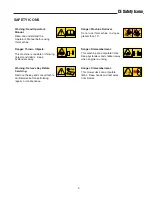
Page 10: ...essages on your rider and mower should be carefully read and obeyed Personal bodily injury can result when these instructions are not followed The information is for your safety and it is important The safety decals below are on your rider and mower If any of these decals are lost or damaged replace them at once See your local dealer for replacements These labels are easily applied and will act as...

Page 11: ... Warning Remove Key Before Servicing Remove the key and consult techni cal literature before performing repairs or maintenance Danger Machine Rollover Do not use this machine on slopes greater than 10 Danger Dismemberment This machine can amputate limbs Keep bystanders and children away when engine is running Danger Dismemberment This mower deck can amputate limbs Keep hands and feet away from bla...

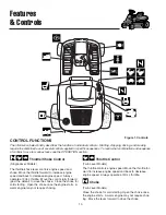
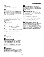
Page 12: ...e throttle controls engine speed Move the throttle for ward to increase engine speed and back to decrease engine speed Always operate at FULL throttle Choke Twin Lever Models Close the choke for cold starting Open the choke once the engine starts A warm engine may not require chok ing Move the lever forward to close the choke CONTROL FUNCTIONS The information below briefly describes the function o...

Page 13: ...nd speed control pedal Moving the lever forward will increase ground speed Note that the further forward the lever is moved the faster the tractor will travel Parking Brake The parking brake knob is used to lock the parking brake when the tractor is stopped Fully depressing the brake pedal and pulling up on the knob engages the parking brake Refer to page 10 for a full explanation of parking brake...

Page 14: ...empt to bypass safety switches and never tamper with safety devices Check their operation regularly Operational SAFETY Checks Your unit is equipped with a seat switch safety system Check the seat switch operation every fall and spring with the following tests Test 1 Engine should NOT crank if PTO switch is ON OR Brake pedal is NOT fully depressed parking brake OFF OR The cruise control lever is NO...

Page 15: ... 1 Seat yourself on the rider seat in the operating posi tion Set the parking brake using the brake pedal D Figure 3 and parking brake knob B 2 Disengage the PTO clutch 3 Set the throttle to FULL 4 Close the choke NOTE A warm engine may not require choking 5 Insert the ignition key and turn it to START 6 After the engine starts move the engine throttle con trol to SLOW Warm up the engine by runnin...

Page 16: ...ne throttle M Figure 1 to 1 2 throttle setting and allow the engine to idle for 20 seconds Stopping a hot engine too fast may cause engine damage 5 Turn key C Figure 1 to OFF and remove it Figure 4 Controls A Mower Lift Lever D Clutch Brake Pedal B Parking Brake Knob E Dial A CutTM Control C Ground Speed Control Lever OPERATING THE MOWER 1 When traveling to or from the work site fully raise the mo...

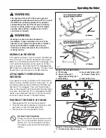
Page 17: ... WARNING The engine will shut off if the reverse ground speed pedal is depressed while the PTO is on and the RMO has not been activated The operator should always turn the PTO off prior to driving across on roads paths or any area that maybe used by other vehicles Sudden loss of drive could create a hazard MOWING IN REVERSE If an operator chooses to mow in reverse the RMO sys tem can be used To us...

Page 18: ...ee inset illustration Figure 7 NOTE Pull back slightly on the lift lever to allow easier turning of the Dial A CutTM control Figure 7 Mower Removal Installation 34 mower shown A Idler Pulley Arm D Lift Cable B Idler Pulley E Lift Hook C PTO Electric Clutch Pulley F Rear Trailing Arms 2396 Figure 8 Mower Hitch A Lever C Rider Hitch Brackets B Mower Hitch 2390 5 Remove mower hitch B Figure 8 from ri...

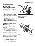
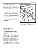
Page 19: ...arning WARNING Never store the unit with fuel in an enclosed poorly ventilated structure Fuel vapors can travel to an ignition source such as a furnace water heater etc and cause an explosion Fuel vapor is also toxic to humans and animals Battery life will be increased if it is removed put in a cool dry place and fully charged about once a month If the battery is left in the unit disconnect the ne...

Page 20: ...es may differ slightly from the Max Inflation stamped on the side wall of the tires The pressures shown provide proper traction improve cut quality and extend tire life SAFETY ITEMS Before Each Use Every 5 Hours Every 25 Hours Every 100 Hours Every 250 Hours Spring Fall Check Safety Interlock System Check Tractor Brakes Check Mower Blade Stopping Time TRACTOR MAINTENANCE ITEMS Before Each Use Ever...

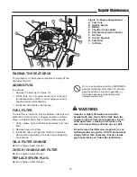
Page 21: ... slide hose clamps from fuel filter 2 Remove hoses from filter 3 Install new filter in proper flow direction in fuel line Secure with hose clamps See warning at beginning of procedure OIL FILTER CHANGE Refer to engine owners manual CHECK CHANGE AIR FILTER Refer to engine owners manual REPLACE SPARK PLUG Refer to engine owners manual WARNING Gasoline is highly flammable and must be handled with car...

Page 22: ...se When an oil can is shown wipe the area clean apply a few drops of oil SAE 30 then wipe up drips or spills 2388B Figure 11 Brake Pedal Pivot Point Figure 12 Front Axle Lubrication Points Figure 14 Rider Lubrication Points Rear Half Gear Model Shown Figure 13 Mower Deck Lubrication Points Figure 15 Rider Lubrication Points Front Half 2390 Figure 16 Arbor Lubrication Points Note On 30 mower grease...

Page 23: ...e recommend removing the rear wheel hubs and lubri cating the axle shafts yearly This prevents the wheel hubs from seizing onto the axle shaft and makes future service easier 1 Turn off the ignition turn off the PTO engage the parking brake and block the front tires 2 Using a jack or chain hoist positioned at the center of the rear frame carefully jack the unit up until the rear tires are approxim...

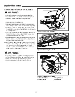
Page 24: ...l each blade with the tabs pointing up toward deck as shown in Figure 21 Secure with a capscrew D cup washer C and hex washer B Use a wooden block to prevent blade rotation and torque capscrews to 45 55 ft lbs 61 75 N m Regular Maintenance Figure 21 Installing The Blade A Wooden Block C Cup Washer B Hex Washer D Capscrew A D C B Torque to 45 55 ft lbs LOOSEN Figure 19 Removing The Blade Figure 20 ...

Page 25: ...ait one minute for automatic reset Replace if defective see your dealer 6 Battery terminals require cleaning 6 See Normal Care section 7 Battery discharged or dead 7 Recharge or replace 8 Wiring loose or broken 8 Visually check wiring replace broken or frayed wires Tighten loose connections 9 Solenoid or starter motor faulty 9 Repair or replace see your dealer 10 Safety interlock switch faulty 10 ...

Page 26: ...flated equally 2 See Normal Care or properly Mower cut is rough looking 1 Engine speed too slow 1 Set to full speed 2 Ground speed too fast 2 Set ground speed control lever at a slower ground speed 3 Blades dull and require sharpening 3 See Servicing the Mower Blades 4 Mower drive belt slipping 4 Belt oily or worn Clean or replace belt as necessary 5 Check PTO Electric Clutch 5 Clutch may need to ...

Page 27: ...d to the steering shaft 1 See Figure 23 Loosen the two capscrews A and push bracket so that gear teeth are closely meshed 2 Tighten nuts after adjustment Torque to 35 40ft lbs STEERING WHEEL ADJUSTMENT Your unit is equipped with a dual position steering shaft to allow for steering wheel adjustment for rider comfort 1 Pull down on the rubber boot to expose the two holes in the steering shaft A Figu...

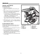
Page 28: ... brake Loosen or tighten adjustment nut H to achieve a 1 5 8 1 3 4 compressed spring length as shown in Figure 24 BLADE BRAKE CHECK Mower blades and mower drive belt should come to a complete stop within five seconds after electric PTO switch is turned off 1 With rider in neutral PTO disengaged and operator in seat start the rider engine 2 Look over the left hand footrest at the mower drive belt E...

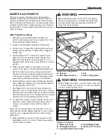
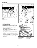
Page 29: ...necessary to perform transport height adjustment again after all leveling procedures are completed 6 Position blade s side to side and measure distance from outside tip of blade s to ground Measurement should be equal within 1 8 7 See Figure 28 On left side of mower make sure eccentric nut is in correct position as shown Loosen outside nut A and rotate eccentric nut B so that flat side with hole c...

Page 30: ...rom ground to rear tip of blade s On 30 mower the front tip should be level to 1 8 3 mm higher than rear tip On 34 mower the front tips should be 1 4 6 mm higher than the rear tips 3 See Figure 29 Loosen jam nut E To lower rear of mower deck loosen nut B which will lengthen level ing rod D To raise rear of deck shorten leveling rod D When proper measurement is obtained tighten nut A against bracke...

Page 31: ...397 Figure 30 Transport Height Adjustment A Spacers C Nut B Rear Mower Rollers D Rear Trailing Arms BATTERY CHARGING A dead battery or one too weak to start the engine may be the result of a defect in the charging system or other electrical component If there is any doubt about the cause of the problem see your dealer If you need to replace the battery follow the steps under Cleaning the Battery C...

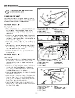
Page 32: ...l belt on PTO pulley E MOWER BELT 34 See Figure 32 1 Mower does not need to be removed to install a new belt However for easier access mower can be removed following steps in Mower Removal and Installation 2 If mower is not removed place mower in lowest cut ting position Push idler pulley arm A Figure 32 away from you to relieve belt tension Remove belt from idler pulley B and PTO pulley C 3 Remov...

Page 33: ...ing and are subject to change without notice The power ratings for an individual engine model are initially developed by starting with SAE Society of Automotive Engineers code J1940 Small Engine Power Torque Rating Procedure Revision 2002 05 Given both the wide array of products on which our engines are placed and the variety of environmental issues applicable to operating the equipment it may be ...

Page 34: ...manuals currently available for your model contact our Customer Publications Department at 262 284 8519 Simplicity 866 313 6682 Snaper Have the information listed in the box below available when phoning in your request Technical manuals can be downloaded from www simplicitymfg com www snapper com Twin Bag Grass Catcher Dump Cart Hour Meter Kit Gas Can Front Weight Engine Oil Touch Up Paint Grease ...

Page 35: ......

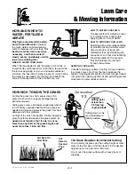
Page 36: ... through the summer AERATING YOUR LAWN Consider aerating your lawn in spring Using an aerator to remove cores of soil from the lawn increases the speed of clipping decomposition and encourages deeper root growth by opening up the soil and permitting greater movement of water fertilizer and air TP 600 2136 03 UV SMA HOW HIGH TO MOW THE GRASS Cutting the grass too short causes weak thin grass plants...

Page 37: ...ulch when the grass is wet moist grass does not mulch well and clumps beneath the mower deck Note Always operate the engine at full throttle when mowing PROPER MOWING SPEED ENGINE SPEED GROUND SPEED Always operate the engine at full throttle when mowing If you hear the engine slowing down you are mowing too fast maintaining a slower ground speed will improve the cutting efficiency of the blades an...

Page 38: ......

Page 39: ......

Page 40: ...ox 997 Port Washington WI 53074 0997 www SimplicityMfg com 500 N Spring Street PO Box 997 Port Washington WI 53074 0997 www AGCOLawn com PRODUCTS INC 535 Macon Street McDonough GA 30253 www Snapper com Briggs Stratton Yard Power Products Group Copyright 2006 Briggs Stratton Corporation Milwaukee WI USA All Rights Reserved ...

Reviews: