background image

4

Introduction

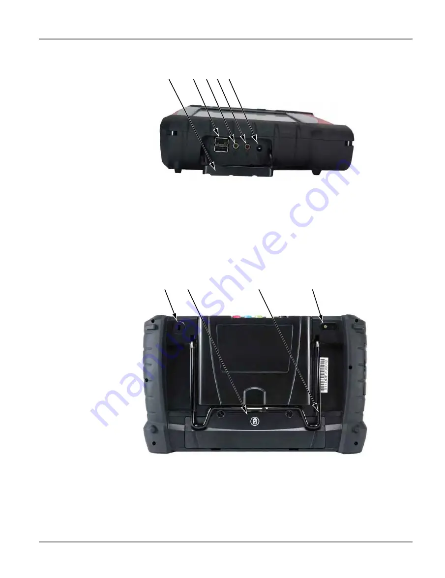
Display Device

1— Hinged Cover

2— USB (universal serial bus) Ports (2)

3— Head Phone Jack

4— Microphone Jack

5— DC Power Supply Input Port

Figure 2-2 Model D10 side view

1— Kennsington Lock (standard security device connection, device not included)

2— Battery Compartment Cover

3— Collapsible Stand (closed)

4— Camera Lens

Figure 2-3 Model D10 back view

/HIW6LGHRI8QLW

Summary of Contents for D10

Page 1: ...User Manual August 2012 EAZ0077L00A Rev B ...

Page 2: ... of the purchase lease or rental agreement under the terms of which the equipment to which this manual relates was acquired Increases in any way the liability to the customer or to third parties Snap on reserves the right to make changes at any time without notice IMPORTANT Before operating or maintaining this unit please read this manual carefully paying extra attention to the safety warnings and...

Page 3: ...te and acceptable manner that does not endanger your safety the safety of others in the work area the equipment being used or the vehicle being tested It is assumed that the operator has a thorough understanding of vehicle systems before using this product Understanding of these system principles and operating theories is necessary for competent safe and accurate use of this instrument Before usin...

Page 4: ...onsequences of not avoiding the hazard An icon when present gives a graphical description of the potential hazard Example 51 1 Risk of unexpected vehicle movement Block drive wheels before performing a test with engine running A moving vehicle can cause injury Important Safety Instructions For a complete list of safety messages refer to the accompanying Important Safety Instructions SAVE THESE INS...

Page 5: ...iption 7 Technical Specifications 8 Power Sources 8 Scope Multimeter Module 9 Functional Description 9 Technical Specifications 10 Power Sources 10 Chapter 3 Getting Started 11 Powering Up 11 Module Buttons 11 Toolbar 13 Windows Toolbar 16 Powering Down 17 Emergency Shutdown 17 Chapter 4 Navigation 18 Controls and Features 18 Control Buttons 18 LEDs 19 The Stand 19 Camera Operation 19 Chapter 5 Sc...

Page 6: ...th Check 52 Global OBD II Code Check 53 Global OBD II Clear Codes 54 Readiness Monitors 54 MIL Status 54 OBD Diagnose 55 Start Communication 55 Select Communication Protocol 58 Connector Information 59 Chapter 7 Component Test Operations 60 Vehicle Identification 60 Creating a Favorites List 61 Identifying a Test Vehicle 62 Operations 64 Component Information 64 Tests 65 Chapter 8 Scope Multimeter...

Page 7: ... Open 108 New 108 Delete 109 Rename 110 Save 111 Properties 111 More 112 Saved File Structure 112 Chapter 13 Help Operations 113 Using the Help Toolbar 113 Chapter 14 System Settings Operations 114 Paired Devices 114 Pairing the Scan Module 115 Shop Information 116 Chapter 15 Maintenance 118 Display Device 118 Cleaning the Touch Screen 118 Calibrating the Touch Screen 118 Cleaning and Inspecting t...

Page 8: ...tton 1 1 2 Symbols Different types of arrows are used The greater than arrow indicates an abbreviated set of selection instructions Example Select Utilities Tool Setup Date The example statement abbreviates the following procedure 1 Navigate to the Utilities screen 2 Highlight the Tool Setup submenu 3 Highlight the Date option from the submenu 4 Press OK to confirm the selection The solid arrows r...

Page 9: ...y result in damage to the test equipment or vehicle Example IMPORTANT Do not disconnect the data cable while the Scanner is communicating with the ECM 1 1 5 Hyperlinks Hyperlinks or links that take you to other related articles procedures and illustrations are available in electronic documents Blue colored text indicates a selectable hyperlink Example IMPORTANT Read all applicable Safety Informati...

Page 10: ...cessing vehicle data Scope Multimeter Module the device for sampling circuits and signals This manual describes the construction and operation of these three devices and how they work together to deliver diagnostic solutions 2 1 Display Device 2 1 1 Functional Description 1 Audio Speaker 2 Power Indicator LED light emitting diode 3 Microphone 4 Hard Drive Activity LED 5 Directional Buttons left ri...

Page 11: ...ead Phone Jack 4 Microphone Jack 5 DC Power Supply Input Port Figure 2 2 Model D10 side view 1 Kennsington Lock standard security device connection device not included 2 Battery Compartment Cover 3 Collapsible Stand closed 4 Camera Lens Figure 2 3 Model D10 back view HIW 6LGH RI 8QLW ...

Page 12: ...attery Lithium Ion Smart Battery Pack Approximate 4 hour run time Approximate 4 hour charge time with or without unit operating DC Jack Operating Voltage 10V to 32V DC Communications 802 11 b g n Wireless Bluetooth 2 1 EDR Dimensions Width 13 23 inches 336 1 mm Height 8 07 inches 205 mm Depth 2 41 inches 61 3 mm Weight including battery pack and Scope Multimeter Module 5 1 lbs 2 31 kg Weight inclu...

Page 13: ...charged standard battery provides sufficient power for about 4 5 hours of continuous operation A LED on the front of the unit indicates the battery state of charge AC DC Power Supply The display unit can be powered from a wall socket using the AC DC power supply The AC DC power supply also powers the internal battery pack charging process Vehicle Power The display unit can be powered from a standa...

Page 14: ...for access Figure 2 4 Scan Module Wireless Communication The Scan Module is a wireless communications device that transmits vehicle data to the display device without a physical connection The working range of the transmitter is about 30 feet 9 14 m A signal lost due to moving out of range automatically restores itself when the display unit is brought closer to the Scan Module The Scanner sounds a...

Page 15: ... C Storage Temperature ambient At 0 to 70 relative humidity non condensing 4 to 140 F 20 to 60 C Environmental Conditions This product is intended for indoor use only This product is rated for Pollution Degree 2 normal conditions 2 2 3 Power Sources The Scan Module operates on 12V or 24V vehicle power which it receives through the data cable connector The unit powers on whenever it is connected to...

Page 16: ...evice and is held in place by a lock tab Depress the lock tab and the Scope Multimeter Module is easily removed from the Display Device A USB cable supplied with your kit can then be used to connect the Scope Multimeter Module to the Display Device Now you can continue to remotely monitor circuit activity while moving the Display Device around the vehicle 51 1 87 21 5 6 2 3 26 21 0 8 1 9 3256 1 1 ...

Page 17: ...0 to 45 C Storage Temperature ambient At 0 to 70 relative humidity non condensing 4 to 140 F 20 to 60 C Environmental Conditions This product is intended for indoor use only This product is rated for Pollution Degree 2 normal conditions 2 3 3 Power Sources The Scope Multimeter Module operates on USB power 5V 500mA supplied by the Display Device Power is provided either through direct connection to...

Page 18: ...wering Up Press the Display Device Power button to switch the unit on The system boots up then opens the Home screen Figure 3 1 1 Module Buttons 2 Toolbar 3 Windows Toolbar Figure 3 1 Sample Home screen 3 1 1 Module Buttons The Module buttons configure the Display Device for the type of test to be performed Table 3 1 on page 12 gives brief descriptions of the available Module buttons which operati...

Page 19: ... a Tech website See Ask a Tech Operations on page 93 Information Provides the information needed to make repairs once you have made your diagnosis The linked program varies by region See Information Operations on page 100 Vehicle History Identifies the test vehicle and organizes and manages work in progress and service records See Vehicle History Operations on page 101 Data Manager Opens the organ...

Page 20: ...ta currently being viewed Selecting opens a submenu Save available from the Scan Module opens an additional submenu with these options Screenshot saves a graphic image of the current screen Collected Data saves a recording of all the data currently in the buffer plus the number of frames designated after the trigger event see Properties on page 44 Table 3 2 Module buttons Name Button Description H...

Page 21: ...e file Edit This Scan Module option performs the same function as the Alarms button on the Scanner Toolbar For more information refer to Alarms on page 43 Setup This Scan Module option allows you to adjust tool settings to your personal preferences Selecting Tools opens a submenu that includes the following Graph Properties Unit Setup Download Firmware Display BEN Graph Properties Selecting opens ...

Page 22: ...in damage to the unit NOTE i It is recommended to connect the unit to an AC power source when downloading firmware Display BEN This option shows the BEN of the currently identified vehicle in the Scanner toolbar The BEN is a unique identifier that is used internally for data coordination and communication Table 3 3 Scan tool units of measurement Setting Default Option Vacuum manifold pressure kPa ...

Page 23: ...device and all other modules User s Manuals This Scan Module option opens a submenu of support documentation such as vehicle communication software manuals These manuals provide connection and test information for specific vehicles Selecting a menu item opens a printable PDF version of the document in a separate window About Component Test This option opens a dialog box that contains software vers...

Page 24: ...le communicating may lead to ECM problems on some vehicles Exit the Scan Module before powering down z To power down the Display Device 1 Navigate to the Home screen 2 Select the Exit button 3 From the Windows desktop open the Windows Start menu 4 Select Turn Off Computer 5 Select Turn Off in the dialog box The open programs close and the power switches off 3 2 1 Emergency Shutdown In case of emer...

Page 25: ...ibe the external controls and features of the display device 4 1 1 Control Buttons Name and location of control buttons All other tool operations are controlled through the touch screen Table 4 1 Display Device control buttons Name Button Description S Button A function button that provides a shortcut for capturing a screen image Directional Buttons Moves the cursor or highlight on the display scr...

Page 26: ...r storage and pivots out so the display is at a 45 degree angle when in use 4 2 Camera Operation A single press of the Camera button on the front of the Display Device activates the camera With the camera active the touch screen becomes the view finder and is also used for reviewing photographs that are taken Buttons on the touch screen are used to operate the camera The buttons change depending o...

Page 27: ...he shutter repeat steps 2 3 and 4 to take additional pictures 5 Select Exit from the live view to close the camera application Photographs are stored on the hard drive and can be retrieved from the desktop by selecting My Documents ShopStream Camera Folder Back Displays in Gallery mode Selecting returns to the previously viewed screen Previous Displays in Gallery mode Selecting opens the picture p...

Page 28: ...ce to establish a wireless communication link Refer to Pairing the Scan Module on page 115 for details A demonstration program allows you to become familiar with Scanner operations and testing without being connected to an actual vehicle 5 1 1 The Demonstration Program The Scanner demonstration program allows you to become familiar with many of the test capabilities without connecting to a vehicle...

Page 29: ...cted database 5 Follow the on screen instructions and select as needed until the Systems menu displays 6 Select from any of the systems listed then select from the submenus IMPORTANT Do not connect a vehicle to the Scan Module while in the Demonstration mode 5 1 2 Disconnecting the Diagnostic Platform From a Vehicle When disconnecting the Diagnostic Platform from the vehicle make sure the Scanner ...

Page 30: ...ore removing the test cable or powering down 5 2 Vehicle Identification The Scanner information presented is provided by a direct link to the ECM of the test vehicle Therefore certain attributes of the test vehicle must be entered into the Diagnostic Platform so that the data displays correctly Vehicle identification information is carried over if you enter the Scan Module either from the Componen...

Page 31: ...g Configure Favorites from the toolbar See Creating a Favorites List on page 61 for details 3 Select the year of the test vehicle from the menu A list of vehicle types or models displays Several selections may be required to identify the vehicle type and model follow the screen prompts and enter the required information A confirmation dialog box displays once all the required data has been entered...

Page 32: ...native Vehicle Identification Occasionally you may identify a test vehicle that the Scanner does not recognize the database does not support or has some unique characteristics that prevent it from communicating with the Scanner through the normal channels In these instances a menu of alternate choices that allow you to establish communication with the vehicle by other means displays In addition to...

Page 33: ...uit voltage and current A green LED also on the vehicle connector end of the cable illuminates whenever there is power supplied to the cable An LED that fails to illuminate indicates either a problem on the vehicle power circuit or a blown data cable fuse All OBD II EOBD vehicles have vehicle battery power B available on the DLC so the Scan Module should power on as soon as the cable is connected ...

Page 34: ...ting that the vehicle is not equipped with such as ABS There is a loose connection There is a blown vehicle fuse There is a wiring fault on the vehicle or in the data cable or adapter There is a circuit fault in the data cable Personality Key or adapter Incorrect vehicle identification was entered Refer to the Vehicle Communication Software manuals for manufacturer specific problems 5 4 Navigation...

Page 35: ...urns to the previously viewed screen Custom Allows you to select which parameters are displayed on the screen Alarms Allows you to set an alarm on certain data parameters when the signal goes above or below the alarm setting Properties Allows you to adjust the display characteristics for all of the data screens Graph View Allows you to simultaneously view up to 16 data graphs at a time Save Saves ...

Page 36: ...ion Go To Start Moves to the first frame in the data buffer Pause Suspends data capture and changes to show the Play button Play Starts or resumes data capture and changes to show the Pause button Go To End Moves to the last frame in the data buffer Clear Erases data in the data buffer Step Back Moves to the previous frame in the data buffer Frame Counter Indicates the data buffer frame currently ...

Page 37: ...ven program that presents a series of choices one at a time As you select from a menu the next menu in the series displays Each selection narrows the focus and leads to the desired test Use your fingertip or the stylus to make menu selections 5 5 Operations The Scanner allows you to establish a data link to the electronic control systems of the vehicle being serviced in order to view live data par...

Page 38: ... reprogram adaptive values for certain components after making repairs Selecting opens a submenu These options are found on the Functional Tests Menu for some models System Tests provides specific subsystem testing Performing these tests is similar to functional tests Generic Functions lets you access certain available Generic OBD II functions from a proprietary menu 1996 and newer vehicles only T...

Page 39: ...r the selected module The items available for any control module vary from one vehicle to another Data is presented in a 2 column format An abbreviated parameter name is at the left of each column and its value is at the right edge of the column Parameters display in the order that they are transmitted by the ECM so expect variation between vehicles Gesture scrolling allows you to quickly move thr...

Page 40: ... buffered information is automatically saved as a movie This gives you a complete picture of what was happening before the fact what occurred at the trigger point and what happened after the fact Data collection is paused following a trigger event Select the Play button to resume viewing live data A vertical line now appears on each of the data graphs to indicate the triggering point The trigger l...

Page 41: ...e box and the minimum and maximum fields activate Figure 5 15 Figure 5 15 Sample Graph Properties dialog box 3 Tap either Max maximum or Min minimum to activate that field and open the keyboard 4 Type the desired trigger value into the field 5 Tap the other field and enter a trigger value then close the virtual keyboard 6 Tap Save to close the dialog box Trigger lines blue for upper and red for lo...

Page 42: ...r to resume viewing live data NOTE i Selecting an armed Snapshot button disarms it Scale Scale adjusts the upper and lower values displayed on the vertical axis of a data graph Two scale modes are available auto scale and manual scale Auto scale which is the default setting automatically adjusts the graph scale based upon the minimum and maximum values transmitted by the ECM Manual scale allows yo...

Page 43: ... Buffer toolbar allow you to change the magnification level of the sweep when viewing data graphs Use the Zoom In button to increase magnification and the Zoom Out button to decrease magnification 5 5 2 Codes Menu This selection may appear as Codes Codes Menu Codes Only codes No Data or something similar on the menu Selecting opens a list of data parameter viewing options that may include Display ...

Page 44: ...erlinks to sources of more detailed information about the code module Figure 5 19 Figure 5 19 Sample code list Selecting the information button on the right side of the code field opens the dropdown menu Clear Codes The Scanner clears trouble codes from the control module memory on some vehicles If this function is not available on the test vehicle Clear Codes does not appear as a menu option z To...

Page 45: ...M commanded the malfunction indicator lamp MIL to turn on DTC Status This selection allows you to view the records of a particular DTC z To check DTC status 1 Select DTC Status from the Codes Menu The DTC Status entry field displays and the virtual keyboard opens Figure 5 20 Figure 5 20 Sample DTC Status entry field 2 Use the virtual keyboard to enter the characters of the DTC 3 Tap the virtual ke...

Page 46: ...ponent such as a solenoid relay or switch between two operating states Variable Control Tests command a certain value for a system or component such as varying the spark timing in 1 increments or the EGR valve duty cycle in 10 increments Reset Tests reset the adaptive or learned values that are stored in the control module Selecting Functional Tests opens a menu of test options that varies by make...

Page 47: ...eneric function refer to the Global OBD Vehicle Communications Software Manual Menu options typically include Table 5 5 Functional test control buttons Name Button Description Test Activates the test Return Moves focus back to the data list Change List Allows you to switch data lists Custom Allows you to select which parameters display during the functional test Minus Switches an item to low or of...

Page 48: ...the root cause of a particular problem The tips are vehicle specific which means only tips that relate to the identified vehicle are presented Troubleshooter appears in a Scanner menu only if tips are available for the system selected on the identified vehicle Selecting opens a Troubleshooter Menu that typically includes Code Tips provides detailed information on setting conditions testing and int...

Page 49: ... allows you to focus on any suspicious or symptom specific data parameters You can add or remove most parameters from the list Any parameter that has a lock icon next to it cannot be removed from the list IMPORTANT Limiting the number of parameters to display only those that apply to a particular situation allows for a faster refresh rate of the data A smaller data lists also reduces the amount of...

Page 50: ...d return to the data list Use the List View button to return to a data screen in PID List format Use the Graph View button to return to a data screen in Graph View format see Graph View on page 45 for details NOTE i Graph View is only available when 16 or fewer parameters the number that can display on a single screen were selected for the custom list Make sure that no more than 16 parameters are ...

Page 51: ...The Properties button on the Scanner Toolbar is used to configure certain characteristics of the parameter graph display Selecting opens a Properties dialog box that allows you to adjust colors settings and sweep Figure 5 26 Selecting either color option Edit Plot Color or Edit Background Color opens a standard color selection dialog box select a color then tap OK to close the dialog box The Show ...

Page 52: ...rial data by the control module Graph View Graph View allows you to simultaneously display up to 16 parameter graphs Figure 5 27 The graphs must first be opened in the data list in order to be included when Graph View is selected from the toolbar The display defaults to a single graph if more than 16 graphs are open when the toolbar button is selected Should this happen return to the data list and...

Page 53: ... to record movies of vehicle datastream values Saved files and be helpful when trying to isolate an intermittent problem or to verify a repair during a road test z To save a movie Select Save A save movie dialog box displays while data is being saved The movie is saved when the message box disappears Figure 5 28 Sample save dialog box Saved files can later be viewed by selecting Data Manager on th...

Page 54: ...be opened into an internet browser z To open a saved print file 1 Minimize the Diagnostic Suite to view the desktop 2 From the desktop select My Documents ShopStream Scanner Data Folder 3 Locate the file you wish to view 4 Double tap the file to open it The internet browser launches and the file opens More Whenever the More button appears on the toolbar it indicates that there are additional optio...

Page 55: ...oses once a selection is made Figure 5 31 Sample data graph sweep 5 6 Exiting the Scanner The Scanner remains open as long as there is an active communication link with the vehicle You must disconnect this communication link in order to exit from Scanner tests and close the Diagnostic Platform software A warning message displays if you attempt to shut down while the Scanner is communicating with a...

Page 56: ...S Diagnostic Platform Firmware updates increase the Scan Module diagnostic capabilities typically by adding new tests new models or enhanced applications to the databases The display device automatically searches for available updates for all of the VERUS components when it is connected to the internet Any updates that are found are downloaded and stored on the device However the update must be in...

Page 57: ...d cover on the base of the Scan Module to expose the USB port c Plug the small end of the USB cable into the USB port on the Scan Module d Plug the large end of the USB cable into one of the ports on the side of the display device 1 Hinged cover 2 USB port Figure 5 33 Scan Module service port NOTE i The Scan Module and Display Device must be connected with the USB cable to update the firmware The ...

Page 58: ...een A Reprogramming succeeded message displays once the installation process is complete Figure 5 35 Figure 5 35 Sample firmware update complete message 5 Select OK to close the message and return to Scanner operations The Scan Module with the latest firmware update is now ready to use ...

Page 59: ...II EOBD compliant vehicles that are not included in the Scanner databases OBD Direct is a Scanner function and the Scan Module must be connected to the test vehicle and communicating with the Display Device This function only provides generic OBD II EOBD information To access enhanced OBD II EOBD functions select Scanner from the Home screen Selecting OBD Direct on the Home screen opens a menu wit...

Page 60: ...differences between makes Pending Codes The purpose of this service is to enable the scan tool to obtain pending or maturing diagnostic trouble codes These are codes whose setting conditions were met during the last drive cycle but need to be met on two or more consecutive drive cycles before the DTC actually sets The intended use of this service is to assist the service technician after a vehicle...

Page 61: ...onal information 6 1 3 Readiness Monitors Use this menu option to check the readiness of the monitoring system An OBD II EOBD system checks the status of emission related subsystems by running continuous or periodic tests Test results are shown in the data viewer Figure 6 3 Figure 6 3 Sample readiness monitor test report Gesture sweep to view the entire list of Readiness Monitors to ensure that al...

Page 62: ...t models 6 2 1 Start Communication Use the following procedure to conduct an OBD Direct test session z To perform an OBD Direct Test 1 Select Start Communications from the OBD Direct menu A generic connection message displays Figure 6 4 connect the Scan Module to the test vehicle as instructed Figure 6 4 Sample generic connection message 2 Select Continue A communications message that shows how ma...

Page 63: ...ystem If a monitor system is not supported it is not displayed Scroll if needed to view the entire list of monitors Selecting Readiness Monitors opens a submenu with two choices Monitors Complete Since DTC Cleared displays the results of all monitor tests that have run since the last time the electronic control module ECM memory was cleared Monitors Complete This Cycle displays only the results of...

Page 64: ...uts and system status information broadcast on the vehicle data stream 02 Display Freeze Frame Data This item is used to display freeze fame data for any stored emission related diagnostic trouble codes DTC In most cases the stored frame is the last DTC that occurred Certain DTCs those that have a greater impact on vehicle emission have a higher priority In these cases the highest priority DTC is ...

Page 65: ...libration verification number CVN of the test vehicle 09 In use Performance Tracking This selection displays the In use Performance Tracking of monitored data It is basically a record of the number of times each of the monitor tests have been completed 6 2 2 Select Communication Protocol A communication protocol is a standardized way of data communication between an ECM and a scan tool Global OBD ...

Page 66: ...e difficult to find test connector z To locate a vehicle diagnostic connector 1 Select Connector Information from the System menu 2 Select a manufacturer from the list presented 3 Select a model from the list presented Instructions for which if any cable adapter or pin to use displays 4 Select Continue Information on where to locate the vehicle diagnostic connector displays 5 Select Continue to re...

Page 67: ...ystems do not use this product for Measurement Categories II III and IV Measurement Category I is for performing measurements on circuits not directly connected to MAINS or MAINS circuits an example of a MAINS circuit is 120V AC or 240V AC household or industrial electricity do not connect this product to MAINS or MAINS circuits Do not apply the Black Ground Lead to test points other than ground s...

Page 68: ...d A toolbar at the top of the screen allows you to custom configure the manufacturer list to display only the makes you frequently service Figure 7 1 Sample manufacturer list z To custom configure the manufacturer list 1 Tap Configure Favorites on the toolbar A list of selectable manufacturers displays Figure 7 2 Sample Configure Favorites screen 2 Tap each manufacturer you want to include selecte...

Page 69: ...y selecting Configure Favorites from the toolbar 7 1 2 Identifying a Test Vehicle Exact procedures to identify the test vehicle may vary somewhat by vehicle and market The following procedure which identifies a 2008 Ford Focus for testing the fuel injection system is typical of what to expect z To identify a vehicle for Component Test 1 Tap the Component Test module button from the Home screen 2 S...

Page 70: ...ays Figure 7 5 Figure 7 5 Sample available tests list 9 Select a test to continue The identification sequence is now complete refer to the Operations section that follows for details on how to navigate through the Component Test information and perform tests NOTE i If you return to the Home screen and select Scanner or Information the vehicle identification entered here is carried over However add...

Page 71: ...ing time 7 2 1 Component Information Component Information provides details on specific vehicle components to provide a better understanding the components prior to diagnosis The Component Information screens contain information to assist you with testing The screens are divided in sections to help quickly guide you to the correct information Figure 7 6 Figure 7 6 Sample Component Information scre...

Page 72: ...t It also provides specifications tips on how and where to connect the test meter leads and also automatically configures the multimeter or lab scope to perform the selected test Once a test vehicle is identified you can select a component from the available tests list z To select a test 1 Select a component from the list 2 Select TEST to open the list NOTE i More than one selection is available i...

Page 73: ...g additional information or open an additional window on top of the current screen Hyperlinks display as buttons Common hyperlinks are View Meter opens a live meter set up to perform the test in the lower portion of the screen Figure 7 9 Once the meter view is open the Component Test toolbar at the top of the screen is replaced by the Scope Multimeter toolbar which allows you to make adjustments t...

Page 74: ...to the Scan Module and can be accessed from the Windows toolbar at the bottom of the screen You can also resize and reposition the meter window on the screen Figure 7 10 Sample meter view in a separate window Tapping the Close button red box with an X when viewing the meter in a separate window closes the meter and returns you to the Component Test screen 3 Tap the Meter button a third time to clo...

Page 75: ...e test procedure to connect the test leads Performing a Test Once you connect the test leads to the vehicle you can proceed with testing z To perform component tests 1 Follow the instructions displayed in the test procedure section 2 Gesture sweep to view all of the instructions and follow the on screen procedures 3 Select the View Meter hyperlink to display test results 4 Refer to the on screen i...

Page 76: ...or industrial electricity do not connect this product to MAINS or MAINS circuits Do not apply the Black Ground Lead to test points other than ground system return vehicle chassis Electrical shock can cause personal injury equipment damage or circuit damage IMPORTANT Maximum rated transient over voltage impulse is 500 volts do not exceed the rated transient over voltage 8 1 Remote Scope Multimeter ...

Page 77: ...ure 8 2 Scope Multimeter module USB port location 4 Connect the square end of the USB cable to the port on the Scope Multimeter 5 Open the hinged cover on the left hand side of the Display Device Figure 8 3 1 Hinged cover 2 USB ports Figure 8 3 Scope Multimeter module USB port location 6 Connect the rectangular end of the USB cable to either of the two ports on the Display Device The Scope Multime...

Page 78: ...l input is referenced to common ground input GND black banana jack Sample Rate 1 5 MSPS Continuous sampling MSPS mega samples per second Bandwidth DC 3 MHz 3 db point 3 MHz Input Impedance 10 MOhm DC 4 kOhm 3 MHz Channel 1 4 VDC Full Scale 75VDC Do not measure greater than 75VDC VAC Full Scale 50VAC Do not measure greater than 50VDC rms Low Amp Probe 20A scale 100mV Amp 40A scale 10mV Amp Connect ...

Page 79: ...annel 1 Figure 8 4 and other channel connections that need additional grounding The lead color matches the color of socket 1 on the Display Device and the color of trace 1 on the test screens This yellow lead includes a black right angle common ground plug and a black stackable common ground plug The non stackable ground plug always connects to the ground GND port on top of the unit The stackable ...

Page 80: ...Figure 8 7 is used for either Channel 4 or Digital Meter plus The lead color matches the color of socket 4 on the Display Device as well as the color of trace 4 on the test screen Alligator Clips Figure 8 8 Alligator clip Insulated alligator clips colored to match each test lead are included A black clip for the common ground lead is also supplied Figure 8 8 Each clip plugs into the straight end o...

Page 81: ...ition lead on the vehicle to display ignition patterns Inductive RPM Pickup Adapter optional Figure 8 12 Inductive RPM Pickup adapter The optional Inductive RPM Pickup adapter Figure 8 12 connects to the scope auxiliary port of the Display Device with a DB9F plug It can be used to trigger a waveform or display RPM With the Ignition Scope the RPM Pickup connects to cylinder number one to establish ...

Page 82: ...on the toolbar let you select how tests display on the screen Trace Details displays trace settings which can be adjusted or switched through the touch screen Record Playback Control Toolbar allows you to record and navigate through paused data 1 Scope Multimeter toolbar 2 Main body 3 Trace Details 4 Record Playback Control toolbar Figure 8 14 Scope Multimeter screen layout Scope Multimeter Toolba...

Page 83: ...er the Data button on the upper toolbar or the Touch and Grow button on the Playback toolbar Both buttons function the same and cycle the Trace Details selection through three states Displayed trace settings are displayed in this mode Explanded trace settings are displayed in a larger format in this mode Off trace settings are not displayed in this mode Table 8 4 Scope Multimeter toolbar buttons N...

Page 84: ...al sampling rate in order to capture fast events such as spikes glitches and other anomalies that may normally be undetected Filter smooths out the trace when the signal is disrupted by noise or other interference Inverted switches the polarity of the displayed signal Coupling AC subtracts the average value of the waveform by blocking the DC portion of an input signal to amplify the AC portion Thi...

Page 85: ...kly move through paused data Figure 8 16 Sample data buffer slider Use the toolbar buttons Table 8 5 to more precisely navigate the data Table 8 5 Data buffer toolbar buttons part 1 of 2 Name Button Description Snapshot Arms the software to take a snapshot of the sampled data Step Back Moves to the previous point in the recorded data Back 1Frame Moves to the previous frame in the recorded buffer S...

Page 86: ...ction to close the dialog box 8 4 Operations This section describes configuring the scope or meter and performing tests 8 4 1 Starting the Scope and Multimeter Use the following procedure to set up the scope multimeter for performing tests z To start the scope multimeter 1 Select the Scope Multimeter button on the Home screen The Scope Multimeter main menu a list of setup options displays Lab Scop...

Page 87: ...s Lab Scope Options The following options are available for testing 4 Channel Lab Scope Volts DC Low Amps 20 Low Amps 40 Low Amps 60 Ignition Probe 100 psi Vacuum 100 psi Pressure 500 psi Pressure 5000 psi Pressure MT5030 Vacuum MT5030 Pressure EEDM506D Temperature Ignition Scope Options The following options are available for testing Parade Cylinder Raster Superimposed Single Cylinder Ignition Gr...

Page 88: ...nd Multimeter Setup The following sections explain how to adjust the scope and multimeter for the specific type of signal being sampled Most of these setup operations are available from the toolbar Trace Controls The Trace controls are used to adjust individual characteristics of how the signal is sampled and displayed for each of the four traces z To adjust trace controls 1 Select Setup from the ...

Page 89: ...s reversed when checked normal when not checked Coupling AC check when sampling an AC signal uncheck for DC signals Peak Detect use when trying to capture a fast event or signal glitch Filter use when radio frequency interference RFI may be disrupting the signal 9 The scope samples the signal and internally calculates the best way to display it when Auto Find is selected A scale and the vertical p...

Page 90: ...he scope Trigger Controls Triggering allows you to set the scope so that it only begins displaying a trace once predetermined signal conditions or triggers are met The trigger point is indicated by a plus sign on the scope grid The plus sign can be dragged across the grid with the stylus to roughly position it The trigger controls allow you to precisely position the trigger z To adjust trigger con...

Page 91: ...ot found message displays Manual if a trigger is found the waveform displays If a trigger is not found nothing displays no waveform and no message 3 Slope sets triggering to the rising top button or falling lower button slope of the signal waveform 4 Vertical position moves the trigger position up and down on the grid 5 Horizontal position moves the trigger timing left and right on the grid 6 Sele...

Page 92: ...are discussed in the following sections 3 Make dialog box selections as needed 4 Select Back to return to the Preferences dialog box or select Exit to close the dialog box and return to the scope Display Settings Selecting Display from the View submenu opens the Display dialog box Figure 8 20 Figure 8 20 Sample Display dialog box The following options are available from the Display dialog box Show...

Page 93: ...tings The selected radio knob on the Layout dialog box shows which setting is active Use the stylus to switch between settings 1 Window shows all traces on the same screen Figure 8 23 2 Windows shows two separate traces in two ways horizontal one below another Figure 8 24 or vertical side by side Figure 8 25 3 windows shows three traces one below another on the same screen Figure 8 26 4 windows sh...

Page 94: ...87 Scope Multimeter Operations Operations Figure 8 24 Sample 2 Windows horizontal display Figure 8 25 Sample 2 Windows vertical display Figure 8 26 Sample 3 Windows display ...

Page 95: ...meter toolbar The Scope Multimeter Preferences dialog box opens 2 Select Setup from the dialog box A submenu of options displays Back use to return to the Preferences dialog box Units use to set how measurement values display US standard or metric Snapshot use to adjust the percentage of data captured following a trigger event Ignition use to configure the ignition scope for the test vehicle Selec...

Page 96: ...ch range from ten to ninety percent in ten percent increments are shown as buttons with the current setting highlighted Select a button then select Back or Exit to close the dialog box Figure 8 29 Sample Snapshot dialog box Refer to Trigger Controls on page 83 for information on how to setup a trigger Abbreviation Description bar bar inHg inches of mercury kg cm2 kilograms per centimeter squared k...

Page 97: ...or coil on plug systems Other use for systems that do not fit any of the above categories 4 Select the number of cylinders for the test vehicle in the Cylinders field Scroll through the list using the up and down arrows on either side of the number 5 This step varies depending upon the type of ignition system If testing a Standard system select the Firing Order If testing an Other system select th...

Page 98: ...n Drag the slider or tap the arrows to position the cursors Each tap of the stylus moves the cursor incrementally in the direction of the arrow Select Show to display the cursors the button changes to Hide Select Hide to conceal the cursors the button changes to Show Select Back to close the dialog box Refresh Controls Selecting the Refresh button from the Scope Multimeter Toolbar clears the minim...

Page 99: ... the information panel of the Data Manager 4 Use the keyboard to enter a description of the file to be saved 5 Select the OK button or tap return on the keyboard 6 Select OK to close the file setup dialog box Once a configuration is saved it becomes available as a preset Files are saved to the Scope Multimeter Data Folder and can be retrieved through the Data Manager Print Controls Selecting Print...

Page 100: ...ity of Ask a Tech users Tips display as a list on the website with an icon along the right hand edge The icons indicate the type of information the tip includes and how the tip was developed Icon Type of Tip Description Certified This Tip has been subject to strenuous quality control Community members are free to comment on or edit the Tip to improve it As soon as a Certified Tip is edited it beco...

Page 101: ...ehicle b Select Cancel to identify a different vehicle Figure 9 1 Sample confirmation message 2 A vehicle identification sequence begins if there is no active vehicle Follow the screen prompts to a Select the year b Select the make c Select the model Select OK when the confirmation message displays The Ask a Tech website launches once the vehicle identification is confirmed 9 3 Ask a Tech Home Pag...

Page 102: ...ge varies depending upon a number of factors the type of tip the complexity of the issue and what is required to resolve the situation Tip pages allow you to track the complete history of a tip from the original question to the verified repair Figure 9 3 Icon Name Description Question Indicates a question a member is asking of the group Answer Indicates an answer a member has posted in response to...

Page 103: ...ons allow you to personalize the Ask a Tech experience My Open Questions provides a quick way to check for responses to questions you have posted Vehicle identification is carried over from the diagnostic platform when you enter Ask a Tech and displays just below the search field The Change Vehicle button to the left of the search field allows you to change the vehicle or modify its attributes Sel...

Page 104: ... Use the scroll bar at the right of the results to view the entire page Use the Showing page bar at the bottom of the page to navigate between pages To limit the number of results be more specific in your search criteria Select a tip from the search results to open it View Latest Questions This option allows you to review the most recent questions members have posted to the group selecting opens a...

Page 105: ... to the community Figure 9 6 Figure 9 6 Sample ask a question page There are five fields to be filled in on the question form Subject Symptoms Diagnostic Steps Performed Parts Replaced Your Question Attachments Subject and Symptoms are required and Ask a Tech does not accept a question unless there is information these fields The other fields are optional but the more detail you provide the more t...

Page 106: ...orm Title enter a name for your Tip Enter Tip Content enter the text and attachments to be included in your Tip Subscribe for Notifications sends you an e mail notice whenever a member comments on or edits your Tip Save Tip submits your Tip to Ask a Tech FAQ The FAQ frequently asked questions option listed under Contribute in the left hand panel of the Ask a Tech home page opens a document that de...

Page 107: ...es that help you fix the problem and get the vehicle back in service Figure 10 1 Figure 10 1 Sample Home screen Information button ShopKey5 software is available as an option for North America An internet connection is required When installed simply tap the Repair information toolbar button to launch the ShopKey5 program Refer to the on line help within the ShopKey5 program for additional informat...

Page 108: ...y and can only start after a Vehicle History is opened 11 1 Screen Layout There are two main parts to the Vehicle History screen 1 Vehicle History Toolbar lets you manage the vehicle data 2 Main Body lists all open Vehicle History records Figure 11 1 Sample Vehicle History screen 11 1 1 Vehicle History Main Body The main body of the screen lists all of the available Vehicle History items By defaul...

Page 109: ... Activate Use this button to load an existing vehicle history when servicing a vehicle that you have previously worked on The Diagnostic Platform uses the identification characteristics stored in the vehicle history to load the correct database so there is no need to identify the test vehicle Table 11 1 Toolbar buttons Name Button Description Back Returns to the previously viewed screen Activate L...

Page 110: ... an existing Vehicle History z To modify an existing Vehicle History 1 Highlight the Vehicle History be opened in the main body of the screen 2 Tap View on the Vehicle History toolbar The worksheet for the selected vehicle opens and there are now Back and Save Close buttons available on the toolbar Figure 11 2 Sample vehicle history worksheet NOTE i The virtual keyboard automatically opens the fir...

Page 111: ...e 11 3 Sample Search dialog box z To search 1 Tap Search on the Vehicle History toolbar to open the search window 2 A dropdown menu allows you to select the field to search Year Make Model Color Customer License State Technician 3 Use the virtual keyboard to enter search criteria into the text field 4 Select Search to start the search The display returns to the Vehicle History screen with only the...

Page 112: ... Settings 1 Tap Settings on the Vehicle History toolbar to open the dialog box Figure 11 4 Sample Settings dialog box 2 Tap to highlight the categories that you do not want to display on the main screen remember Items that are highlighted do not display Items that are not highlighted display 3 Select OK on the toolbar to implement the changes select Cancel to disregard the changes The dialog box c...

Page 113: ...file when available and the preview panel on the lower right displays an image if the selected file is a graphic 1 Data Manager Toolbar 2 Folders Panel 3 Preview Panel 4 Information Panel Figure 12 1 Sample Data Manager main screen The main screen includes folders for saved files from the various modules Camera Folder contains photographs taken with the built in camera CTM Data Folder contains fil...

Page 114: ...d is shown near the top of the screen just above the toolbar Table 12 1 Data Manager toolbar buttons Name Button Description My Data Returns to the Data Manager main screen Up Moves the items displayed in the folders panel up one level in the file structure Open Opens the highlighted folder or file New Creates a new folder Delete Moves the highlighted file or folder to the recycling bin Rename Ope...

Page 115: ...en a folder 1 Highlight the file to open in the folders panel 2 Tap the Open button to load the highlighted file Figure 12 2 Sample open folder showing information The screen advances and the contents of the open folder are shown in the folders panel Highlight an item in the folders panel and the information or preview displays if available in the lower portion of the screen Figure 12 2 3 To exit ...

Page 116: ...folder and return to the previous page The Cancel button returns you to the previous page without creating a new folder Figure 12 3 Sample New Folder name dialog box 12 3 5 Delete The Delete button moves folders or items within folders to the Recycling bin A confirmation displays when a file is selected for deletion Select Yes to delete the file or No to cancel z To delete an item 1 Touch to highl...

Page 117: ...No button returns you to the previous page without deleting the selected item 12 3 6 Rename The Rename button allows you to change the name of a folder or items within a folder z To rename an item 1 Highlight the item or folder to be renamed 2 Tap the Rename button on the toolbar The New Name dialog box opens Figure 12 3 Figure 12 5 Sample new name dialog box ...

Page 118: ...es Operation is similar to renaming a file as discussed above except there are additional fields for entering descriptive information z To assign properties to an item 1 Highlight the item or folder 2 Tap the Properties button on the toolbar The Properties dialog box and the virtual keyboard open Figure 12 3 Figure 12 6 Sample Properties dialog box without the virtual keyboard 3 Type a new name in...

Page 119: ...th the selected file attached The display device must have an active e mail account to use this feature 12 4 Saved File Structure The Diagnostic Suite automatically creates folders to manage saved files Whenever 60 files are saved into any of the Data Manager menu option folders a new folder is created Folders may contain files for a day week month or a year An Older folder when available goes to ...

Page 120: ... the top of the screen is used to adjust screen magnification and to exit Help Table 13 1 Help toolbar buttons Name Button Description Back Closes the help file and returns you to the previously viewed screen Zoom Incrementally increases the screen magnification Zoom Incrementally decreases the screen magnification Reset Restores the default screen magnification Previous Page Moves back one page i...

Page 121: ...nnection so that data is readily available while working anywhere on the vehicle In order to do this the modules need to be paired or synchronized the first time they are used together Detailed information about paired modules can be found by selecting System Settings from the Home screen z To check paired module details 1 Tap the System Settings button on the Home screen 2 Tap the Paired Devices ...

Page 122: ... the Display Device 2 Connect the 25 pin end of the data cable to the Scan Module data cable port 3 Connect the 16 pin end of the data cable to a live vehicle data link connector DLC The green vehicle power LED should be illuminated 4 Tap the System Settings button on the Home screen of the Display Device 5 Select Paired Devices from the menu 6 From the Paired Devices screen select Add from the to...

Page 123: ... from the vehicle The Scan Module and Display devices are now paired for wireless communication and should automatically recognize each other when both are powered up 14 2 Shop Information This option allows you to add personalized shop information that can be included on printed data files Selecting opens a form that can be filled in using the virtual keyboard Select OK when the form is complete ...

Page 124: ... the form NOTE i The screen does not scroll Use the Top and Bottom buttons on the right side of the virtual keyboard relocate the keyboard on the screen so that you can complete the form Figure 14 5 Figure 14 5 Virtual keyboard Top and Bottom buttons 5 Close the virtual keyboard and review the information once all the fields have been filled in 6 Select OK from the toolbar to save the Shop Informa...

Page 125: ...d alcohol or a mild window cleaner IMPORTANT Do not use any abrasive cleansers or automotive chemicals on the touch screen 15 1 2 Calibrating the Touch Screen The touch screen can be calibrated for accuracy using the PenMount PM utility of the unit z To calibrate the touch screen 1 From the Windows toolbar select Start PenMount Control Panel Figure 15 1 Launching the calibration program 2 In the P...

Page 126: ...ate the screen 4 Touch and hold the center of each red box that displays in sequence Figure 15 3 Sample calibration target 5 Select OK to close the dialog boxes once the calibration is complete Extended Desktop Touch Screen Calibration Special consideration must be given to calibrating the touch screen when the Extended Desktop feature of theD7 Display Device is used with an external monitor and t...

Page 127: ...5 Select Apply 6 Close the dialog boxes and the Control Panel window 7 Calibrate the touch screen using the standard procedure NOTE i This method disables the extended desktop The same calibration issue arises if the extended desktop is used again z To calibrate the touch screen with the unit installed in docking cradle 1 With the Display Device installed in the docking cradle connect a USB keyboa...

Page 128: ...ctors for dirt and damage before and after each use At the end of each work day wipe the Display Device housing wiring and connectors clean with a damp cloth IMPORTANT Do not use any abrasive cleansers or automotive chemicals on the Display Device 15 1 4 Battery Service Follow all safety guidelines when handling the battery pack 51 1 Risk of electric shock Prior to recycling the battery pack prote...

Page 129: ...ren Do not use a battery pack that appears to have suffered abuse or damage Charge the battery pack in the appropriate charger only Do not use a battery charger that has been modified or damaged Use the battery pack for the specified product only Store the battery pack in a cool dry well ventilated area NOTE i The battery pack should be used within a short period of time about 30 days after chargi...

Page 130: ...attery pack is fully seated 6 Tighten the two captive screws Disposing of the Battery Pack Always dispose of a lithium ion battery pack according to local regulations which vary for different countries and regions The battery pack while non hazardous waste does contain recyclable materials If shipping is required ship the battery pack to a recyling facility in accordance with local national and in...

Page 131: ...erating the tool when the low battery warning displays do not begin charging until after the tool has automatically shut down 3 Fully charge the battery pack NOTE i It is not recommended to perform the calibration procedure more than once within 30 days 15 1 5 Operating System Restore Snap on System Restore is a hard disk drive recovery program that allows you recover the hard disk drive files in ...

Page 132: ...sers or automotive chemicals on the Scan Module 15 2 2 Replacing the Protective Handgrip The soft protective handgrip that covers the outer edges of the Scan Module is easily replaced should it become worn or damaged Contact your sales representative for replacement parts z To replace the protective handgrip 1 Disconnect the data cable and any other cables if attached to the Scan Module 2 From the...

Page 133: ...t please contact Snap on using our information below You may contact us at Snap on Incorporated 2801 80th Street P O Box 1410 Kenosha WI 53141 1410 PERMITTED USES YOU MAY i install the Software on a single automotive diagnostic computer the diagnostics tool for which it was intended provided you keep the original solely for backup or archival purposes ii transfer the Software and License to anothe...

Page 134: ... the Software not meeting the Limited Warranty and which is returned to Snap on at your expense with a copy of the sales receipt THE FOREGOING IS SNAP ON S ENTIRE LIABILITY AND YOUR SOLE AND EXCLUSIVE REMEDY RELATING TO BREACH OF THE LIMITED WARRANTY If failure of the Software has resulted from accident abuse misuse or misapplication Snap on shall have no responsibility whatsoever Any replacement ...

Page 135: ...ALL DEFENSES OF LACK OF PERSONAL JURISDICTION AND FORUM NON CONVENIENS THE PARTIES HEREBY EXPRESSLY AGREE THAT THIS AGREEMENT SHALL NOT BE GOVERNED BY THE UNITED NATIONS CONVENTION ON CONTRACTS FOR THE INTERNATIONAL SALE OF GOODS GENERAL You agree that this Agreement is the complete and exclusive statement of the Agreement between you and Snap on which supersedes any proposal or prior agreement or...

Page 136: ...ly provide to us via the Software or other means Additional information may be collected such as vehicle specific information including vehicle year make model engine and other vehicle data via the software Snap on agrees not to disclose or use any Customer s specific company or end customer data shared with Snap on except to the extent necessary to carry out its obligations under this Agreement w...

Page 137: ...ct us using the information below to ask us to remove your Personal Information from our records electronic or otherwise However we will need to maintain certain Personal Information about your product purchases in our records for purposes such as warranty and product information We will usually be glad to update your information but we reserve the right to use Personal Information obtained previo...

Page 138: ...n 60 63 component tests 39 65 66 connecting to a vehicle 26 31 68 Connector Information 59 D Data Display 31 32 Data display 31 Data Manager 106 112 operations 108 112 properties 111 screen layout 106 toolbar 107 data parameters displaying 31 36 delete 104 demonstration programs 21 diagnostic connector 59 location 59 diagnostic trouble codes DTCs 31 digital meter 73 dimensions unit 5 8 10 Disconne...

Page 139: ... 7 specifications 8 10 Troubleshooter 57 wireless communication 7 Scanner actuator tests 31 alarms 43 checking codes 53 cleaning 125 clear codes 31 54 codes menu 31 36 39 communication protocol 58 component tests 39 connecting 26 custom data list 42 43 data 32 36 demonstration program 21 disconnecting 22 exiting 48 functional tests 31 39 generic functions 31 40 52 58 handgrip replacement 125 memor...

Page 140: ... tests 39 Toolbar 13 116 Vehicle History 102 toolbar record playback controls 78 Scanner 42 trigger condition 34 Triggers setting 34 trouble codes See diagnostic trouble codes DTCs Troubleshooter 31 41 57 Troubleshooter software See software U Units Setup 88 V variable control tests 39 Vehicle History 101 105 activate 102 delete 104 operations 102 105 screen layout 101 search 104 settings 105 tool...

Page 141: ...an be determined by turning the equipment off and on the user is encouraged to try to correct the interference by one or more of the following measures Reorient or relocate the the receiving antenna Increase the separation between the equipment and receiver Connent the equipment into an outlet on a circuit different from that to which the receiver is connented Consult the dealer or an experienced ...

Page 142: ...e limits in ANSI IEEE C95 1 1992 and Canada RSS 102 and had been tested in accordance with the measurement methods and procedures specified in OET Bulletin 65 Supplement C and Canada RSS 102 This device has been tested and meets the FCC IC RF exposure guidelines when tested with the device directly contacted to the body The FCC has granted an Equipment Authorization for this model phone with all r...

Reviews: