

ZL3-TF2Z370EN
Page 1 of 2
Instruction Manual
Multistage Ejector
Series ZL3/ZL6
The intended use of this product is to generate vacuum.
1 Safety Instructions
These safety instructions are intended to prevent hazardous situations
and/or equipment damage. These instructions indicate the level of
potential hazard with the labels of “Caution,” “Warning” or “Danger.”
They are all important notes for safety and must be followed in addition
to International Standards (ISO/IEC)
*1)
, and other safety regulations.
*1)
ISO 4414: Pneumatic fluid power - General rules relating to systems.
ISO 4413: Hydraulic fluid power - General rules relating to systems.
IEC 60204-1: Safety of machinery - Electrical equipment of machines.
(Part 1: General requirements)
ISO 10218-1: Manipulating industrial robots -Safety. etc.
•
Refer to product catalogue, Operation Manual and Handling
Precautions for SMC Products for additional information.
•
Keep this manual in a safe place for future reference.
Caution
Caution indicates a hazard with a low level of risk which, if
not avoided, could result in minor or moderate injury.
Warning
Warning indicates a hazard with a medium level of risk
which, if not avoided, could result in death or serious injury.
Danger
Danger indicates a hazard with a high level of risk which, if
not avoided, will result in death or serious injury.
Warning
•
Always ensure compliance with relevant safety laws and
standards.
•
All work must be carried out in a safe manner by a qualified person in
compliance with applicable national regulations.
2 Specifications
Refer to catalogue for more details.
2.1 ZL3 Series
Model
ZL3M
□□
ZL3H
□□
Nozzle diameter [mm]
1.9
1.5
Standard supply pressure
0.35 MPa
0.50 MPa
Maximum vacuum pressure
*
1
-91 kPa
-93 kPa
Max suction flow rate
*
1
280 L/min(ANR)
Branch, Port exhaust
300 L/min(ANR)
Air consumption
*
1
150 L/min (ANR)
135 L/min (ANR)
Supply pressure range
0.2 to 0.6 MPa
Operating temperature range
-5 to 50
o
C (No freezing or condensation)
Fluid
Air
Vibration resistance
*
2
20 m/s
2
Impact resistance
*
3
100 m/s
2
2.2 ZL6 Series
Model
ZL6M
□□
ZL6H
□□
Nozzle diameter [mm]
1.9 x 2
1.5 x 2
Standard supply
pressure
Without valve
0.35 MPa
0.50 MPa
With valve
0.37 MPa
0.52 MPa
Maximum vacuum pressure
*
1
-91 kPa
-93 kPa
Max suction flow rate
*
1
580 L/min(ANR)
Branch, Port exhaust
600 L/min(ANR)
Air consumption
*
1
300 L/min (ANR)
270 L/min (ANR)
Supply pressure range
0.2 to 0.6 MPa
Operating temperature range
-5 to 50
o
C (No freezing or condensation)
Fluid
Air
Vibration resistance
*
2
20 m/s
2
Impact resistance
*
3
100 m/s
2
NOTE *1)
Values are at the same standard supply pressure and based on SMC’s
measurement standards. They depend on atmospheric pressure (weather, altitude,
etc.) and measurement method.
NOTE *2) 10 to 500Hz for 2 hours in each direction of X, Y and Z (de-energised,
initial value).
NOTE *3) 3 times in each direction of X, Y and Z (de-energised, initial value).
NOTE *4) Refer to operation manual of solenoid valve (JSY3000 series) and
pressure switch (ZSE10 series) for the characteristics.
3 Installation
3.1 Installation
Warning
•
Do not install the product unless the safety instructions have been read
and understood.
•
When mounting the product, tighten with the recommended tightening
torque of the following screws.
- Top surface and side surface mounting: 0.56 to 0.76 N
•m
- Bottom mounting: 0.29 to 0.30 N
•m
•
When installing the product, secure the space required for
maintenance and inspection of the product
•
Do not drop, hit, or apply excessive impact to the product.
3.2 Environment
Warning
•
Do not use in an environment where corrosive gases, chemicals, salt
water or steam are present.
•
Do not use in an explosive atmosphere.
•
Do not expose to direct sunlight. Use a suitable protective cover.
•
Do not install in a location subject to vibration or impact in excess of
the product’s specifications.
•
Do not mount in a location exposed to radiant heat that would result in
temperatures in excess of the product’s specifications
•
This product does not have a built-in suction filter. If there is dust in the
usage environment of the product, consider using a vacuum filter (AFJ
series)
•
Do not use in place where static electricity build-up can occur.
•
Do not use in an environment where surges occur.
3 Installation - continued
3.3 Air Supply
Caution
● Do not use air containing chemicals, synthetic oils containing organic
solvents, salts, or corrosive gases.
● Recommended quality of the supplied air be equivalent to the
compressed air cleanliness grade "2: 6: 3" according to ISO8573-1:
2010.
•
Do not supply the pressure
in excess of the product’s specifications.
3.4 Piping
Caution
•
Before connecting piping make sure to clean up chips, cutting oil, dust
etc
•
When installing piping and fittings, make sure that no sealing material
gets inside the port. When using sealing tape, wind it with one thread
left.
•
Tighten fittings to the specified tightening torque shown in the table
below.
Port type
Port size
Recommended
tightening torque
Vacuum (2/V) port
1/2 or 3/4 (Rc,G,NPT)
28 to 30 N
・
m
Exhaust (3/E) port
1 (Rc,G,NPT)
36 to 38 N
・
m
Vacuum pressure
detection (G) port
1/8 (Rc,NPT)
3 to 5 N
・
m
•
Fix the side of the body when piping to the vacuum (2 / V) port and
pressure detection (G) port and fix the side of the port block when
piping to the exhaust (3 / E) port.
3.5 Wiring to the solenoid valve and pressure switches
Refer to the operation manual of solenoid valve (JSY3000 series) and
pressure switch (ZSE10 series).
4 Settings
4.1 Manual Override (With supply valve and release valve)
Refer to the operation manual of the solenoid valve JSY3000 series
for the manual operation method.
4.2
Release flow adjusting needle
When the release valve is turned on, vacuum break air is let out.
The release flow adjusting needle allows to control the vacuum break air
flow rate.
To adjust the break air flow, pull the push-locking handle to unlock it.
Then, turn the push-locking handle clockwise to reduce the vacuum
break flow, and turn the handle anti-clockwise to increase the flow.
5 How to Order
Refer to the catalogue for
‘How to Order’.
6 Outline Dimensions (mm)
Refer to the catalogue for outline dimensions.
7 Maintenance
7.1 General Maintenance
Caution
•
Not following proper maintenance procedures could cause the product
to malfunction and lead to equipment damage.
•
If handled improperly, compressed air can be dangerous.
•
Maintenance of pneumatic systems should be performed only by
qualified personnel.
•
Before performing maintenance, turn off the power supply and be sure
to cut off the supply pressure. Confirm that the air is released to
atmosphere.
•
After installation and maintenance, apply operating pressure and
power to the equipment and perform appropriate functional and
leakage tests to make sure the equipment is installed correctly.
•
If any electrical connections are disturbed during maintenance, ensure
they are reconnected correctly, and safety checks are carried out as
required to ensure continued compliance with applicable national
regulations.
•
Do not make any modification to the product.
•
Do not disassemble the product, unless required by installation or
maintenance instructions.
•
Implement the maintenance and check shown below to use the
multistage ejector safely and in an appropriate way for a long period of
time.
•
Drain the air filter and mist separator regularly.
•
Replace the sound absorbing material (silencer) built into the ejector
regularly.
•
Refer to the online operation manual for replacement parts.
•
Do not use benzene or thinner for cleaning.
7.2 Replacement method of sound absorbing material (ZL3)
1) Loosen the two mounting screws of the silencer assembly and
remove the silencer case (Fig.1)
2) Replace the sound absorbing material inside the silencer case (Fig.2)
3) Attach the silencer assembly using the mounting screws.
(Recommended tightening torque: 0.76 to 0.84 Nm)
7.3 Silencer assembly (ZL6)
1) Align the hook of the silencer assembly with the groove of the body,
break it, and push it in the direction of the arrow until it clicks.
2) When removing, slide the silencer assembly in the direction opposite
to the mounting direction to remove it.
ORIGINAL INSTRUCTIONS
Manual of supply valve
Manual of release valve
Silencer assembly
Push in until clicks.
Silencer assembly
Assembly
screws
Sound absorbing material
Fig.1
Fig.2
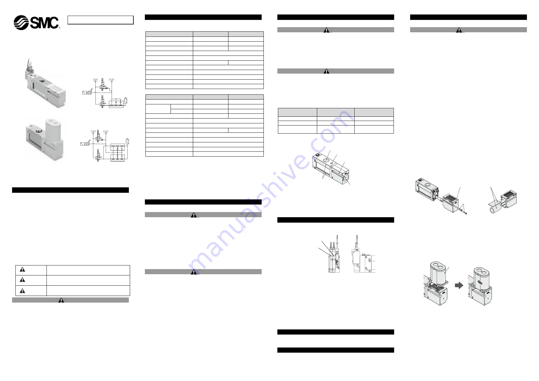
ZL3 Series
ZL6 Series
Body surface to be held
(Width across flats 40)
Exhaust(3/E) port
Exhaust block surface to be held
(Width across flats 40)
Vacuum pressure detection(G) port
Vacuum(2/V) port


