


VR51-TF2Z003EN-A
Page 2 of 3
2 Specifications - continued
Figure 7. UKCA DoC VR51-TF1Z181UK
2.4 Batch code
The batch code indicated in the product label translates to construction
year / month according to the following table (eg. “ZQ = Mar 2021):
Construction
Production batch codes
Year / Month
Jan Feb
Mar
Apr
May
Jun
Jul
Aug
Sep
Oct
Nov
Dec
2022
Ao AP AQ AR
AS
AT AU AV AW AX
Ay
AZ
2023
Bo BP BQ BR
BS
BT BU BV BW BX
By
BZ
…
…
…
…
…
…
…
…
…
…
…
…
…
2025
Do DP DQ DR DS DT DU DV DW DX
Dy
DZ
Table 2.
3 Installation
3.1 Installation
Warning
•
Do not install the product unless the safety instructions have been read
and understood.
•
Do not install the product if it appears to have been damaged during
transport.
•
Do not paint the product.
•
Do not remove or cover up warnings or specifications printed or affixed
to the product.
•
Ensure sufficient space for maintenance activities. When installing the
products, allow access for maintenance.
•
Ensure that the connections of pipework to the unit do not result in a
residual trip hazard to system operators or maintainers.
•
If air leakage increases or equipment does not operate to specification,
stop operation.
•
Check mounting conditions when air supplies are connected. Initial
function and leakage tests should be performed after installation.
3.2 Environment
Warning
•
Do not use in an environment where corrosive gases, chemicals, salt
water or steam are present.
3 Installation - continued
•
Do not use in an explosive atmosphere.
•
Do not expose to direct sunlight. Use a suitable protective cover.
•
Do not install in a location subject to vibration or impact in excess of
the product’s specifications.
•
Do not mount in a location exposed to radiant heat that would result in
temperatures in excess of the
product’s specifications.
•
Employ suitable protective measures in locations where there is
contact with oil or welding spatter etc.
•
Ambient humidity
When using the valve in environments with low humidity, take
measures to prevent static.
If the humidity rises, take measures to prevent the adhesion of water
droplets on the valve.
Do not use in high humidity environment where condensation occurs.
•
Altitude limitation is 1000 m above sea level.
Caution
Avoid using in places where there is splashing oil, coolant or water. In
addition, avoid using where dust may adhere.
3.3 Piping
Caution
•
Before connecting piping make sure to clean up chips, cutting oil, dust
etc.
•
When installing piping or fittings, ensure sealant material does not
enter inside the port. When using seal tape, leave 1 thread
exposed
on the end of the pipe/fitting.
•
Tighten fittings to the specified tightening torque.
•
Connect tubing with a longer length than required to prevent torsion,
stretching or moment loads. Damage of the fittings or flattening, as
well as bursting or releasing of the tubing may occur if the instructions
are not followed.
•
Tubing connected to the VR51 should be used at more than its
minimum bend radius. If used under the minimum bend radius,
bending or flattening of the tubing may occur. Refer to catalogue for
additional information.
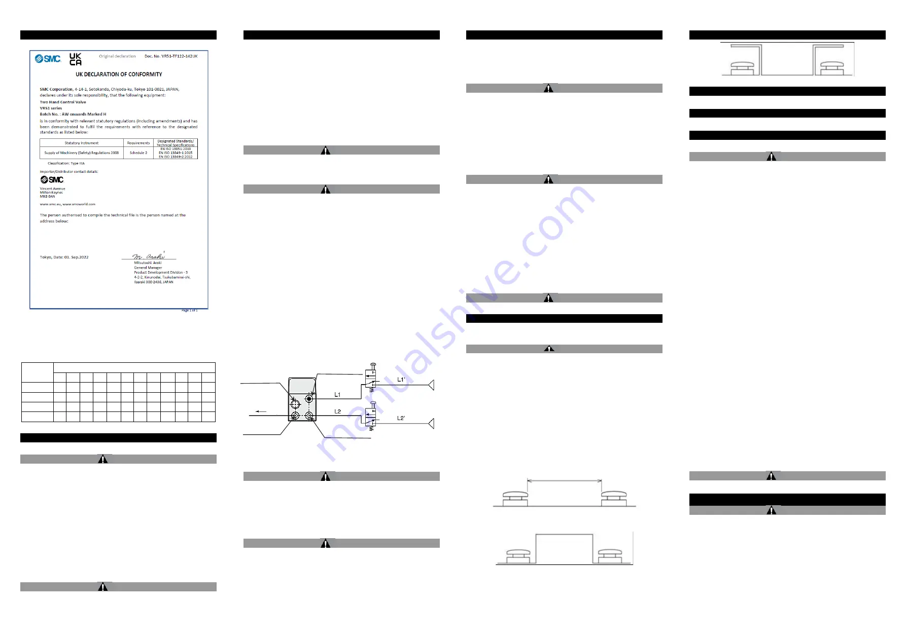
3.3.1 Piping length for secondary side
To help avoid output timing delay;
•
Use the same tubing length and diameter between the VR51 and each
control actuating device: L1=L2, L1
’=L2’.
•
Use the same control valve type for each input port: V1=V2
•
Operate the control valves with the same pressure: P1=P2
Figure 8.
3.4 Lubrication
Caution
•
SMC products have been lubricated for life at manufacture, and do not
require lubrication in service.
•
If a lubricant is used in the system, use turbine oil Class 1 (no additive),
ISO VG32. Once lubricant is used in the system, lubrication must be
continued because the original lubricant applied during manufacturing
will be washed away.
3.5 Air supply
Warning
•
When there is a large amount of condensate.
Compressed air containing a large amount of water vapour can cause
malfunction of pneumatic equipment such as valves. An air dryer or
water separator should be installed upstream from filters.
•
Drain flushing
If condensation in the drain bowl is not emptied on a regular basis, the
bowl will overflow and allow the condensation to enter the compressed
air lines. It causes malfunction of pneumatic equipment.
3 Installation - continued
If the drain bowl is difficult to check and remove, installation of a drain
bowl with an auto drain option is recommended.
•
Type of air
Do not use compressed air that contains chemicals, synthetic oils
including organic solvents, salt or corrosive gases, etc., as it can cause
damage or malfunction.
Caution
•
When extremely dry air is used as the fluid, degradation of the
lubrication properties inside the equipment may occur, resulting in
reduced reliability (or reduced service life) of the equipment. Please
consult with SMC.
•
Install an air filter upstream near the valve. Select an air filter with a
filtration size of 5
μm or smaller.
•
Take measures to ensure air quality, such as by installing an
aftercooler, air dryer, or water separator.
•
If excessive carbon powder is seen, install a mist separator on the
upstream side of the valve.
If excessive carbon dust is generated by the compressor it may adhere
to the inside of a valve and cause it to malfunction.
Warning
•
Minimise the distance between the valve and the air supply and
between the valve and the protected system.
•
Do not place any devices between the valve and the protected system
that might interfere with the safety function.
•
The exhaust ports of the valve should not be left unconnected.
•
The exhaust ports of the valves should never be blocked and must be
protected from ingress of contamination by a suitable silencer or device
which does not affect the valve function.
3.6 Mounting
•
The valve can be mounted using 2 x M5 x 0.8 bolts (thread depth:
5 mm) or using a bracket with 2 x
∅
6.5 mm diameter holes. Tightening
torque for M5 thread is 1.5 to 3 N
∙m.
•
Refer to catalogue for more details.
3.7 One-touch fittings
Caution
Refer to catalogue for specific precautions.
4 Settings
4.1 Operating button setup
Caution
•
Design and prepare the buttons in accordance with instruction
manuals. Install the buttons according to ISO 13851 Safety of
machinery - Two-hand control devices - Functional aspects - Principles
for design and other applicable standards.
•
If the operating buttons are incorrectly arranged, an unexpected
motion is likely to occur and safety cannot be maintained.
•
Principle precautions (reference only):
- Configure the buttons so only 2 hand operation is possible, ensure
it is not possible to operate by 1 hand only.
- Configure the buttons so only 2 hand operation is possible, ensure
it is not possible to operate by forearm(s) or elbow(s).
- Configure the buttons so only 2 hand operation is possible, ensure
it is not possible to operate by 1 hand and any other part of the
body (knee or hip for example).
•
Example of button setup:
- Ensure a safe spacing of the buttons so they cannot be operated
by 1 hand.
Figure 9.
- Install an isolating object between the buttons so they cannot be
operated by 1 hand.
Figure 10.
- Place a cover over both buttons so they cannot be operated by 1
hand.
4 Settings - continued
Figure 11.
5 How to Order
Refer to catalogue
for ‘How to Order’.
6 Outline Dimensions
Refer to
catalogue
for outline dimensions.
7 Maintenance
7.1 General maintenance
Caution
•
Not following proper maintenance procedures could cause the product
to malfunction and lead to equipment damage.
•
If handled improperly, compressed air can be dangerous.
•
Maintenance of pneumatic systems should be performed only by
qualified personnel.
•
Before performing maintenance, turn off the power supply and be sure
to cut off the supply pressure. Confirm that the air is released to
atmosphere.
•
After installation and maintenance, apply operating pressure and
power to the equipment and perform appropriate functional and
leakage tests to make sure the equipment is installed correctly.
•
If any electrical connections are disturbed during maintenance, ensure
they are reconnected correctly and safety checks are carried out as
required to ensure continued compliance with applicable national
regulations.
•
Do not make any modification to the product.
•
Do not disassemble the product, unless required by installation or
maintenance instructions.
7.2 Periodic testing
•
The product should be tested regularly for proper operation of the
safety functions.
•
Testing should be conducted at start-up and then at regular intervals
determined by the end user depending on complete system
requirements. The test should consist of operation of the safety system
and observation of the following, replace product if necessary:
- There are no scratches, dents, corrosion, loose screws, or damage
to the valve body.
- The one-touch fitting is not damaged.
- The tube should not be kinked, crushed or damaged.
- The tube should not be hardened, deteriorated or softened.
- No air leaks.
- The air pressure is in the range of 0.25 MPa to 1 MPa.
- Operate the two operating devices installed on the
‘Input’ side at
the same time and ensure that there is output from port A of VR51.
- The operation timings of the two operating devices installed on the
‘Input’ side are shifted by 0.5 seconds or more, and there is no
output from port A of VR51.
- When one of the operating devices is cancelled while there is
output from port A of VR51, there is no output from port A.
7.2 Maintainable parts
Warning
There are no replaceable parts.
8 Limitations of Use
Warning
•
The system designer should determine the effect of the possible failure
modes of the product on the system.
•
VR51 only offers protection for the person operating it.
8.1 Limited warranty and disclaimer/compliance requirements
Refer to Handling Precautions for SMC Products.
8.2 Type of fluid and pneumatic pressure
•
Do not use fluids other than those specified. The only fluid that can be
used is air.
Output
Supply port: P1(11)
Supply port: P2(12)
Exhaust port R(4)
Output port A(2)
Flame resistant One-
touch fitting:
∅
6,
∅
1/4
Flame resistant One-touch
fitting:
∅
6,
∅
1/4
Flame resistant One-touch
fitting:
∅
6,
∅
1/4
With silencer
(order separately,
see Table 1.)
P2
P1
V2
V1


