SMC Networks SMC2890W-AN, Installation Manual
The SMC Networks SMC2890W-AN is a high-performance wireless router ideal for homes and small businesses. For easy setup and configuration, make sure to download the free Installation Manual from our website. Get detailed instructions and troubleshooting tips to maximize the performance of your router.
Share
Download


Reviews:
No comments
Related manuals for SMC2890W-AN

DWR-116
Brand: D-Link Pages: 8

DWR-113
Brand: D-Link Pages: 47

DSR-500AC
Brand: D-Link Pages: 72

DSL Series
Brand: Lancom Pages: 101

DIR-451 - 3G Mobile Router
Brand: D-Link Pages: 83
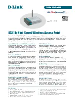
DWL-2100AP - AirPlus Xtreme G
Brand: D-Link Pages: 2

DI-714
Brand: D-Link Pages: 8

DI-711 - Gateway
Brand: D-Link Pages: 7

DI-784
Brand: D-Link Pages: 100

DI-514 - Wireless Router
Brand: D-Link Pages: 62

DIR-L1900
Brand: D-Link Pages: 20

DWP-1010
Brand: D-Link Pages: 47

WA6020
Brand: H3C Pages: 27

QBox610
Brand: Quantenna Pages: 9

WA6120X
Brand: H3C Pages: 33

ALINE-5801A+G
Brand: APM Pages: 2

N150R
Brand: NETGEAR Pages: 92

ALM-N245
Brand: LTE Pages: 47


