- 47 –
No.JXC
※
-OMY0002
9. Operation (example)
9.1 Positioning operation
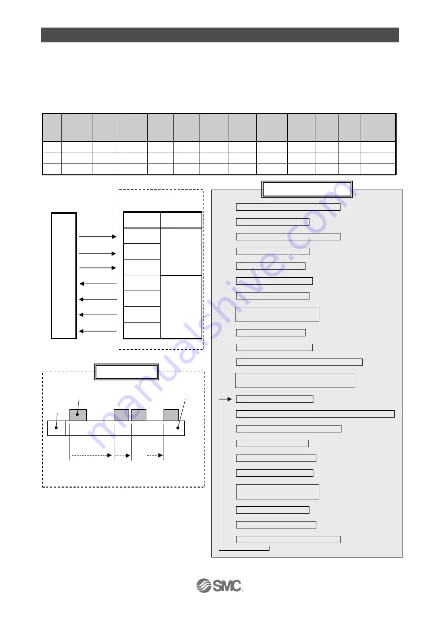
Example) Move the electric actuator from the origin to 50mm point with 100mm/s. (Using Step No.1)
Next, it shows setting example to move the electric actuator from the 50mm point to 100mm point
by moving it 5 times continuously, 10mm at a time, with a speed of 50 mm/s. (Step No. 2)
● [Normal mode] Step data example
No.
Move
ment
MOD
Speed
mm/s
Position
mm
Accele
ration
mm/s
2
Decele
ration
mm/s
2
Pushing
force
%
Trigger
LV
%
Pushing
speed
mm/s
Moving
force
%
Area1
mm
Area2
mm
In position
mm
0
-
-
-
-
-
-
-
-
-
-
-
-
1
Absolute
100
50.00
1000
1000
0
0
0
100
0
0
0.1
2
Relative
50
10.00
1000
1000
0
0
0
100
0
0
0.1
(1) Select/ input No.1 (Turn on IN0)
↓
(2) Turn on DRIVE input.
↓
Start moving to the position of No.1
↓
OUT0 to OUT5 turns off.
↓
(3) INP output turns off.
↓
(4) BUSY output turns on.
↓
(5) Turn off DRIVE input.
↓
(6) OUT0 output turns on
(No.1 output turns on)
↓
(7) INP output turns on.
↓
(8) BUSY output turns off.
↓
Completed to move to the position of No.1.
↓
(9) Select/ input No.2.
(Turn off IN0 input, and turn on IN1)
↓
(10) Turn on DRIVE input.
↓
Start moving to 10mm away from the current position.
↓
No. output OUT0 to OUT5 turns off.
↓
(11) INP output turns off.
↓
(12) BUSY output turns on.
↓
(13) Turn off DRIVE input.
↓
(14) OUT1 output turns on
(No.2 output turns on)
↓
(15) INP output turns on.
↓
(16) BUSY output turns off.
↓
Completed to move to 10mm away.
Operation
Controller
Parallel I/O signal
P
L
C
Signal Category
DRIVE
Input
IN0
IN1
OUT0
Output
OUT1
INP
BUSY
5 times
Electric actuator
0mm
Origin
Motor
Load
・・・
100mm
End position
50mm 60mm
・・・
Flow chart (example)
(2)(5)(10)(13)
(1)
(9)
(6)
(14)
(15)(11)(7)(3)
(16)(12)(8)(4)


