

After unpacking the SMC7908VoWBRA, check the contents of the
box to be sure you have received the following components:
•
One Barricade
TM
ADSL2 Wireless Broadband VoIP Router
•
One Power Adaptor
•
One cable (RJ-11) for connection to the phone line
•
One cable (RJ-45) for LAN connection required to configure
the device.
•
One CD-ROM containing full version of User Manual
•
One Warranty Card
•
One ADSL splitter *
* The ADSL splitter (also called microfilter) is only contained in packages related to specific
countries (US, UK, France, The Netherlands). If your package does not contain a splitter, you may
be required to purchase this item separately. Please contact your ISP for further details.
Please inform your dealer in the event of any incorrect, missing or
damaged parts. If possible, retain the carton and original packing
materials in case there is a need to return the product.
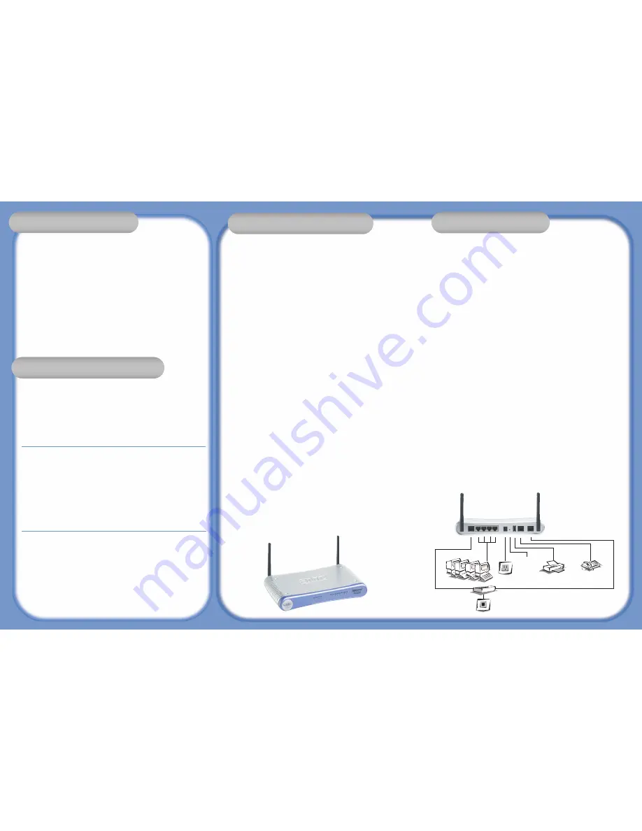
To install and connect to the SMC7908VoWBRA, you must have:
•
An ADSL line installed by your ISP
•
An ADSL splitter (at least one)
•
A Computer with a CD-ROM drive
•
Windows (98 or later), MacOS (9.x)
•
An up to date web browser:
•
Internet Explorer 5.5 or later
•
Mozilla 1.7/Firefox 1.0 or later
Get Connected
Applications
Wireless Networking
Pack
ackage C
age Con
onten
ents
Package Contents
Troubleshooting
Configuration
System Requirements
Hardware Description
Disable HTTP Proxy
Netscape
Explorer
Configuring your Macintosh
Configure TCP/IP Settings
Configure the Barricade g
Netscape
Explorer
Explorer
Configuring your Macintosh
Windows 98SE/ME
Windows 2000/XP
Configure TCP/IP Settings
Configure the Barricade g
Quick Installation Guide
ADSL2 Barricade™ Broadband VoIP Router
with Built-in Annex A ADSL2/2+Modem
SMC7908VoWBRA
Hardware Installation
EZ Installation CD
Initial Configuration
Get Connected
Applications
Wireless Networking
Package Contents
Troubleshooting
Configuration
System R
em Requir
equiremen
ements
System Requirements
Hardware Description
Disable HTTP Proxy
Netscape
Explorer
Configuring your Macintosh
Configure TCP/IP Settings
Configure the Barricade g
Netscape
Explorer
Explorer
Configuring your Macintosh
Windows 98SE/ME
Windows 2000/XP
Configure TCP/IP Settings
Configure the Barricade g
Quick Installation Guide
ADSL2 Barricade™ Broadband VoIP Router
with Built-in Annex A ADSL2/2+Modem
SMC7908VoWBRA
Hardware Installation
EZ Installation CD
Initial Configuration
Get Connected
Applications
Wireless Networking
Package Contents
Troubleshooting
Configuration
System Requirements
Har
Hardw
dwar
are De
e Descrip
cription
tion
Hardware Description
Disable HTTP Proxy
Netscape
Explorer
Configuring your Macintosh
Configure TCP/IP Settings
Configure the Barricade g
Netscape
Explorer
Explorer
Configuring your Macintosh
Windows 98SE/ME
Windows 2000/XP
Configure TCP/IP Settings
Configure the Barricade g
Quick Installation Guide
ADSL2 Barricade™ Broadband VoIP Router
with Built-in Annex A ADSL2/2+Modem
SMC7908VoWBRA
Hardware Installation
EZ Installation CD
Initial Configuration
Front
• Power (PWR) LED -
When this green LED is on, the router is powered up.
• ADSL LED -
This green LED flashes while a link is being set up on the ADSL port.
The LED stays on when the link has been set up and is functioning correctly.
• WLAN LED -
When this green LED is on, wireless networking is enabled. The LED will
flash when data is sent or received over a wireless connection.
• LAN LEDs (LAN1, LAN2, LAN3 and LAN4) -
These green LEDs turn on when there
is an Ethernet connection to the corresponding LAN port on the back panel (see 10
below) and will flash to indicate that data is being sent or received over the connection.
• Line LED -
Shows the PSTN line (FXO port) connection status. When the green LED
is solid, the Phone is OFF-Hook talking on a PSTN call. When the green LED is blinking,
it indicates there is an incoming PSTN call. When the LED is off, there is no activity
• Phone LED -
Shows the phone (FXS port) connection status. When the green LED is
solid, the Phone is OFF-Hook talking on a call. When the green LED is blinking, it
indicates there is an incoming VoIP Call. When the LED is off, the phone is ON-Hook.
• VoIP LED -
Shows the VoIP status. When the green LED is solid, the VoIP link is up
and connected. When the status is blinking green, the router is transmitting and
receiving packets. When the LED is off, there is no connection.
• USB LED -
Shows the USB status. When the green LED is solid, the USB is connected.
When the status is blinking green, the router is transmitting and receiving packets.
When the LED is off, there is no connection.
• PPP LED -
The green LED will blink when a PPP connection is being negotiated and will
remain solid when a PPP connection is made and is functioning properly.
Back
1. ADSL Port
- Use the supplied cable to connect the ADSL port to your ADSL line.
The ADSL LED on the front panel will light up when there is a connection. If you are
using a splitter/filter connect to the port labelled ADSL
2. LAN Ports (1, 2, 3 and 4)
- There are four Ethernet LAN ports for connection to PCs,
network printers or similar devices. Note the labelling; one LAN LED on the front panel is
associated with one port on the rear panel. Port 1 is associated with the LAN1 LED, port 2
with LAN2 and so on. If a device is not correctly connected, using a suitable Ethernet
cable, the associated LED will not turn on.
3. Power
- Connect the supplied, 12V power adapter to this socket.
4. Reset
- You can restart the unit by pressing the reset button and releasing it
immediately. If, for any reason, you need to reset the unit to factory defaults and
cannot access the user interface (e.g. if you have changed and forgotten the
password), press the reset button for 10 seconds. Note that you will lose all your
configuration changes when you reset the router to factory defaults.
5. USB 1.1 Port -
Use this port for connecting USB printer or storage device.
6. RJ-11 FXS Phone Port -
Use these ports to connect to a telephone.
7. RJ-11 FXO Line Port
Use this port to connect to your telephone line. If you are using a
splitter/filter connect to the port labelled phone.
Ethernet cables
Ethernet cables are usually constructed from unscreened, “Cat 5” cable with
RJ45 connecters at both ends. Cables of this type can be purchased at most
computer retailers.
Installation Troubleshooting
• Check that the Power Adapter is both plugged into a working power socket and connected
to the Router. Check the green PWR LED on the Router is turned on. Only use the power
adapter that was supplied with your Router.
• The wired PC should connect to a LAN port of the Router using an Ethernet cable. The
corresponding LAN LED of the Router should be on.
• The Router ADSL port should be connected to your ADSL line. The ADSL LED should be on
when there is a valid connection (synchronization) with your ADSL line.
• Power up your equipment in the following order: First the ADSL Router and then your PC.
Leave at least 30 seconds between turning on each device.
• The PC should be setup to obtain an IP address automatically from the Router's DHCP
server. See the user manual on the CD for details of how to setup your PC to obtain
an IP address.
• Check that web proxy is disabled on your PC. Go to the Control Panel and select Internet
Options. Select the Connections tab and click the LAN Settings button. Check that the
Use Proxy Server option is not ticked.
• Check you can access the Router's web interface. Open a browser and enter
http://192.168.2.1
to access the default IP address of the Router.
WAN Connection Troubleshooting
• Check that you have selected the correct WAN connection option and the ISP details
are correct. If you do not have these details, they can be obtained from your ISP.
• If you have any PPPoE client applications already installed on your PC which were
required when your PC was directly connected to the DSL modem, they must be
disabled.
Wireless Troubleshooting
• Check that the SSID is the same on the Router and the wireless PC.
• Check that the wireless encryption is the same on the Router and the wireless PC. To
help debug a problem, turn off encryption in both the Router and wireless PC until you
can establish a connection. After a change in encryption, some PCs may have to be
restarted.
• The wireless PCs must be set to Infrastructure mode to work with a Router.
• If your computer has both a wired and wireless connection installed, ensure that the
wired Ethernet cable is unplugged.
• Check that the Router WLAN LED is on, to indicate that Wireless networking is
enabled. To enable wireless networking, go to the Router Wireless page and enable
Wireless Networking.
• If there are a number of wireless networks within range, then you may experience poor
wireless performance if the wireless channels are too close together. Ideally,
neighbouring wireless networks should be at least 5 channels apart. The wireless channel is
controlled by and set in the Router.
• The Router has a feature called MAC Filter which controls which wireless PCs have
access to the wireless LAN. If this feature is enabled, then ensure that the MAC address of
your wireless PC card is listed in the MAC Filter page.
Information furnished by SMC Networks, Inc. (SMC) is believed to be accurate and
reliable. However, no responsibility is assumed by SMC for its use, nor for any infringe-
ments of patents or other rights of third parties, which may result from its use. No
license is granted by implication or otherwise under any patent or patent rights of
SMC. SMC reserves the right to change specifications at any time without notice.
SMC Networks, Inc.
38 Tesla
Irvine, CA 92618
Copyright © SMC Networks, Inc., 2004. All rights reserved. SMC is a
registered trademark; and EZ Connect is a trademark of SMC Networks, Inc.
Other product and company names are trademarks or registered
trademarks of their respective holders.
FOR TECHNICAL SUPPORT, CALL:
From U.S.A. and Canada
(24 hours a day, 7 days a week)
(800) SMC-4-YOU
Phn: (949) 679-8000
Fax: (949) 679-1481
From Europe : Contact details can be
found on www.smc.com
INTERNET
E-mail addresses:
[email protected]
Driver updates:
http://www.smc.com/index.cfm?action=
techsupport drivers downloads
World Wide Web:
http://www.smc.com/
If you are looking for further contact
information, please visit www.smc.com
38 Tesla
Irvine, CA 92618
Phone: (949) 679-8000
Model Number: SMC7908VoWBRA
Get Connected
Applications
Wireless Networking
Package Contents
Trouble
oubleshoo
shooting
ting
Troubleshooting
Configuration
System Requirements
Hardware Description
Disable HTTP Proxy
Netscape
Explorer
Configuring your Macintosh
Configure TCP/IP Settings
Configure the Barricade g
Netscape
Explorer
Explorer
Configuring your Macintosh
Windows 98SE/ME
Windows 2000/XP
Configure TCP/IP Settings
Configure the Barricade g
Quick Installation Guide
ADSL2 Barricade™ Broadband VoIP Router
with Built-in Annex A ADSL2/2+Modem
SMC7908VoWBRA
Hardware Installation
EZ Installation CD
Initial Configuration
1
2
3
5
6
7
4
Splitter
Wall Jack


