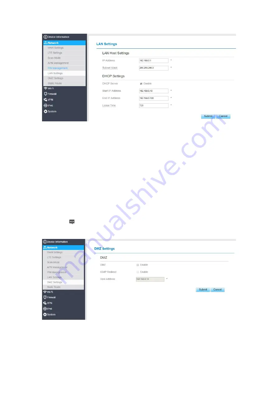
background image

Figure 5- 15

DMZ Settings

If the demilitarized zone (DMZ) is enabled, the packets sent from the WAN are directly sent to a
specified IP address on the LAN before being discarded by the firewall.
To set DMZ, perform the following steps:

1. Choose

Network > DMZ Settings.

2. Set DMZ to

Enable

.

3. (Optional) Set

ICMP Redirect

to

Enable

.

4. Set

Host address

.

This IP address must be different from the IP address set on the

LAN Host

Settings

page, but they must be on the same network segment.

5. Click

Submit

. As shown in Figure 5-18.

Figure 5- 18

Summary of Contents for MGL6201A

Page 1: ...MGL6201A User Manual ...

Page 2: ...put Statistics 11 3 5 Viewing Device List 11 4 Update 12 4 1 Version Manager 12 Viewing Version Info 12 Version Upgrade 12 4 2 Auto upgrade 13 5 Settings 14 5 1 Viewing the Device Information 14 Viewing the Version Information 15 Viewing LAN Status 15 5 2 Viewing Network 16 LTE Settings 16 Scan Mode 18 APN Management 19 PIN Management 20 SIM Lock 22 LAN Setting 22 DMZ Settings 24 Static Route 25 5...

Page 3: ...41 5 8 System 42 5 8 1 Maintenance 42 Reboot 42 Reset 42 Backup Configuration File 43 Upload Configuration File 43 5 8 2 TR069 44 5 8 3 Date Time 45 5 8 4 DDNS 47 5 8 5 Diagnosis 48 Ping 48 Traceroute 49 5 8 6 Port Mirror 50 5 8 7 Syslog 51 Local 51 Network 51 5 8 8 WEB Setting 52 5 8 9 Account 53 5 8 10 Logout 54 6 FAQs 54 ...

Page 4: ...harmful interference to radio communications However there is no guarantee that interference will not occur in a particular installation If this equipment does cause harmful interference to radio or television reception which can be determined by turning the equipment off and on the user is encouraged to try to correct the interference by one or more of the following measures Reorient or relocate ...

Page 5: ... expanding The application scope of MGL6201A such as CPE router data card tablet PC automotive security and industrial PDA etc 1 2Computer Configuration Requirements For optimum performance make sure your computer meets the following requirements Item Requirement CPU Pentium 500 MHz or higher Memory 128 MB RAM or higher Hard disk 50 MB available space Operating system Microsoft Windows XP Windows ...

Page 6: ...odule properly 2 Launch Internet Explorer enter http 192 168 1 1 in the address bar and press Enter As shown in Figure 1 1 Figure 1 1 3 Enter the user name and password and click Log In 4 You can log in to the web management page after the password is verified As shown in Figure 1 2 Figure 1 2 The default user name and password are both admin If you want to view or configure the CPE more you shoul...

Page 7: ...nostic function If you encounter problems please contact customer service for the specific using method To ensure your data safety it is recommended that you turn on the firewall and conserve your login and FTP password carefully ...

Page 8: ... as DL UL Data Rate and Online time As shown in Figure 2 1 Figure 2 1 2 2Viewing LTE Status To view the LTE network status perform the following steps 1 Choose Overview 2 In the LTE Status area view the information about Connect status Mode Cell ID Signal quality and so on As shown in Figure 2 3 Figure 2 3 2 3Viewing WAN Status To view the WAN status perform the following steps ...

Page 9: ...Mask DNS Server and so on As shown in Figure 2 4 Figure 2 4 3 Statistics 3 1Viewing CPU Usage To view the CPU usage perform the following steps 1 Choose Statistics 2 In the CPU Usage area view the CPU usage information such as Current CPU usage Max CPU usage Min CPU usage As shown in Figure 3 1 ...

Page 10: ...ge area view the memory usage information such as Total memory Current memory usage Max memory usage and Min memory usage As shown in Figure 3 2 Figure 3 2 3 3Viewing APN List To view the APN list perform the following steps 1 Choose Statistics 2 In the APN List view the information about APN information As shown in Figure 3 3 ...

Page 11: ...ut and LAN throughput 3 In this area also you can choose and click the button Reset to empty the throughput statistics As shown in Figure 3 4 Figure 3 4 3 5Viewing Device List To view the device list perform the following steps Choose Statistics In the Device List area view the device information which connect to the CPE such as Device name Mac address IP address and Lease time As shown in Figure ...

Page 12: ...e Update Version Manager 2 In the Version Info area you can view the product name and software version As shown in Figure 4 1 Figure 4 1 Version Upgrade To perform an upgrade successfully connect the CPE to your computer through a network cable save the upgrade file on the computer and make sure the CPE is not connected to anything other than a power adapter and the computer To perform an upgrade ...

Page 13: ...pgrade successfully make sure the CPE is connected to the Internet To perform a ftp auto upgrade perform the following steps Choose Update Auto upgrade Enable auto upgrade If you want to check new firmware after connect to Internet you need to enable the item of Check new firmware after connect to Internet Set a ftp address to the Upgrade folder box Set Version file Set User name and Password Set ...

Page 14: ...ettings 5 1 Viewing the Device Information To view the System Information perform the following steps Choose Settings In the System Information area view the system status such as Running time As shown in Figure 5 1 ...

Page 15: ...the device information such as Product name Product Module Hardware Version Software version UBoot version and CPE SN As shown in Figure 5 2 Figure 5 2 Viewing LAN Status To view the LAN status perform the following steps Choose Settings In the LAN Status area view the LAN status such as Mac address IP address and Subnet mask As shown in Figure 5 4 Figure 5 4 ...

Page 16: ...UTER Click Submit As shown in Figure 5 5 Figure 5 5 LTE Settings Settings To set the LTE network perform the following steps 1 Choose Network LTE Settings 2 In the Settings area you can set the configuration of LTE network 3 In the Status area you can view the LTE network connect status such as Frequency RSSI RSRP RSRQ CINR SINR Cell ID and so on As shown in Figure 5 7 ...

Page 17: ...gure 5 8 Auto Connect LTE Network To set the CPE automatically connect to the internet perform the following steps 1 Choose Network LTE Settings 2 In the Setting area set the connect method as Auto when the LTE network is ready the CPE will be connected automaticity As shown in Figure 5 9 Figure 5 9 Manual Connect Mobile Network To set the mobile network manual connect to the internet perform the ...

Page 18: ... in Figure 5 10 Figure 5 10 Scan Mode To set the lte network scan mode perform the following steps choose Network Scan mode You can choose full mode a band the CPE supported Click Submit Setting Frequency Earfcn To set the frequency perform the following steps 1 Choose Network Scan Mode 2 In the Scan Mode area choose Frequency Lock 3 In the Frequency Lock area you can choose a band then click Add ...

Page 19: ...Network APN Management In the APN Management area you can set the APN Choose a APN number which you want to set In the APN Setting area you can set the APN parameters such as enable or disable the apn apn name username password and so on If you want set a APN as default gateway you should check that is enabled Click Submit As shown in Figure 5 12 ...

Page 20: ... following steps 1 Choose Network PIN Management 2 View the status of the USIM card in the USIM card status field Enabling PIN Verification To enable PIN verification perform the following steps 1 Choose Network PIN Management 2 Set PIN verification to Enable 3 Enter the PIN 4 to 8 digits in the Enter PIN box 4 Click Submit Disabling PIN Verification To disable PIN verification perform the followi...

Page 21: ...ing Automatic Verification of the PIN You can enable or disable automatic verification of the PIN If automatic verification is enabled the CPE automatically verifies the PIN after restarting This function can be enabled only when PIN verification is enabled and the PIN is verified To enable automatic verification of the PIN perform the following steps 1 Choose Network PIN Management 2 Set Pin veri...

Page 22: ...192 168 0 1 with a subnet mask of 255 255 255 0 You can change the host IP address to another individual IP address that is easy to remember Make sure that IP address is unique on your network If you change the IP address of the CPE you need to access the web management page with the new IP address To change the IP address of the CPE perform the following steps 1 Choose Network LAN Settings 2 In t...

Page 23: ... LAN or each client must be manually configured To configure DHCP settings perform the following steps 1 Choose Network Setting LAN Settings 2 Set the DHCP server to Enable 3 Set Start IP address This IP address must be different from the IP address set on the LAN Host Settings area but they must be on the same network segment 4 Set End IP address This IP address must be different from the IP addr...

Page 24: ...eing discarded by the firewall To set DMZ perform the following steps 1 Choose Network DMZ Settings 2 Set DMZ to Enable 3 Optional Set ICMP Redirect to Enable 4 Set Host address This IP address must be different from the IP address set on the LAN Host Settings page but they must be on the same network segment 5 Click Submit As shown in Figure 5 18 Figure 5 18 ...

Page 25: ...ce from the drop down list If you select LAN as the interface you need set a Gateway Click Submit As shown in Figure 5 19 Figure 5 19 Modify Static Route To modify an access restriction rule perform the following steps 1 Choose Firewall Static Route 2 Choose the item to be modified and click Edit 3 Repeat steps 3 through 5 in the previous procedure 4 Click Submit As shown in Figure 5 20 ...

Page 26: ...or disable the Parental Controls you can modify the configuration Parental Controls Manager Choose Parental Controls Manager Choose Enable and then click Submit Enabled the Choose Parental function As shown in Figure 5 4 1 Figure 5 4 1 Parental Controls List This page is set the Parental Controls List If this function is enabled you can add some users If someone in this List he was forbidden from ...

Page 27: ...3 5 4 Firewall Setting Firewall This page describes how to set the firewall If you enable or disable the firewall you can modify the configuration To set the firewall perform the following steps Choose Firewall Firewall Setting Choose Enable or Disable to modify the configuration Click Submit As shown in Figure 5 30 ...

Page 28: ...This page enables you to configure the MAC address filtering rules Enabling MAC Filter To enable MAC address filter perform the following steps 1 Choose Firewall MAC Filtering 2 Set MAC filtering to Enable 3 Click Submit As shown in Figure 5 31 Figure 5 31 Disabling MAC Filter To disable MAC address filter perform the following steps 1 Choose Firewall MAC Filtering 2 Set MAC filtering to Disable 3...

Page 29: ...MAC Filtering 2 Set Allow access network within the rules 3 Click Submit As shown in Figure 5 33 Figure 5 33 Setting Deny access network within the rules To set deny access network within the rules perform the following steps 1 Choose Firewall MAC Filtering 2 Set Deny access network within the rules 3 Click Submit As shown in Figure 5 34 Figure 5 34 ...

Page 30: ...tering rule To modify a MAC address rule perform the following steps 1 Choose Firewall MAC Filtering 2 Choose the rule to be modified and click Edit 3 Set MAC address 4 Click Submit As shown in Figure 5 36 Figure 5 36 Deleting MAC Filtering rule To delete a MAC address filter rule perform the following steps Choose Firewall MAC Filtering Choose the rule to be deleted and click Delete As shown in F...

Page 31: ...g To enable IP Filtering perform the following steps 1 Choose Firewall IP Filtering 2 Set IP Filtering Enable 3 Click Submit As shown in Figure 5 38 Figure 5 38 Disabling IP Filtering To disable IP Filtering perform the following steps 1 Choose Firewall IP Filtering 2 Set IP Filtering Disable 3 Click Submit As shown in Figure 5 39 Figure 5 39 ...

Page 32: ...ll IP Filtering 2 Set Deny access network outside the rules 3 Click Submit As shown in Figure 5 41 Figure 5 41 Adding IP Filtering rule Add an IP address filtering rule perform the following steps 1 Choose Firewall IP Filtering 2 Click Add list 3 Set Service 4 Set Protocol 5 In the Source IP Address Range box enter the source IP address or IP address segment to be filtered 6 In the Source port ran...

Page 33: ...tus the rule will be executed 10 Click Submit As shown in Figure 5 42 Figure 5 42 Modifying IP Filtering rule To modify an IP filtering rule perform the following steps 1 Choose Firewall IP Filtering 2 Choose the rule to be modified and click Edit 3 Repeat steps 3 through 9 in the previous procedure 4 Click Submit As shown in Figure 5 43 Figure 5 43 ...

Page 34: ...resource locator URL This page enables you to configure URL filtering rules Enabling URL Filtering To enable URL Filtering perform the following steps 3 Choose Firewall URL Filtering 4 Set URL Filtering to Enable 5 Click Submit As shown in Figure 5 45 Figure 5 45 Disabling URL Filtering To disable URL Filtering perform the following steps 1 Choose Firewall URL Filtering 2 Set URL Filtering to Disa...

Page 35: ...list To modify a URL filtering rule perform the following steps 1 Choose Firewall URL Filtering 2 Choose the rule to be modified and click Edit 3 Set URL address 4 Click Submit As shown in Figure 5 48 Figure 5 48 Deleting URL Filtering list To delete a URL list perform the following steps 1 Choose Firewall URL Filtering 2 Choose the item to be deleted and click Delete As shown in Figure 5 49 Figur...

Page 36: ...e Internet are redirected to the server on the LAN Adding Port Forwarding rule To add a port forwarding rule perform the following steps Choose Firewall Port Forwarding Click Add list Set Service Set Protocol Set Remote port range The port number ranges from 1 to 65535 Set Local host This IP address must be different from the IP address that is set on the LAN Host Settings page but they must be on...

Page 37: ...tem to be modified and click Edit 3 Repeat steps 3 through7 in the previous procedure 4 Click Submit As shown in Figure 5 51 Figure 5 51 Deleting Port Forwarding rule To delete a port forwarding rule perform the following steps Choose Firewall Port Forwarding Choose the item to be deleted and click Delete As shown in Figure 5 52 Figure 5 52 ...

Page 38: ... address 6 Set Weekdays and time 7 Click Submit Modify Access Restriction To modify a access restriction rule perform the following steps 1 Choose Security Access Restriction 2 Choose the item to be modified and click Edit 3 Repeat steps 4 through 6 in the previous procedure 4 Click Submit Delete Access Restriction To delete a access restriction rule perform the following steps 1 Choose Security A...

Page 39: ...PnP perform the following steps 1 Choose Firewall UPnP 2 Set UPnP to Enable 3 Click Submit As shown in Figure 5 54 Figure 5 54 DoS On this page you can enable or disable the Denial of service DoS function 1 Choose Firewall DoS 2 Set UPnP to Enable 3 Click Submit As shown in Figure 5 55 Figure 5 55 ...

Page 40: ...drop down list Enter Username and Password Click Submit You can view the status in VPN Status area As shown in Figure 5 55 Figure 5 55 5 7 IPv6 Internet Protocol version 6 IPv6 is the most recent version of the Internet Protocol IP Every device on the Internet is assigned a unique IP address for identification and location definition Status The status page shows IPv6 information As shown in Figure...

Page 41: ...age user can enable or disable IPv6 function Meanwhile user can set WAN Connection Type and the type of DNS As shown in Figure 5 27 Figure 5 57 IPv6 LAN Settings In this page user can chose the AutoConfiguration Type As shown in Figure 5 58 ...

Page 42: ...rm the following steps 1 Choose System Maintenance 2 Click Reboot As shown in Figure 5 59 The CPE then restarts Figure 5 59 Reset This function enables you to restore the CPE to its default settings To restore the CPE perform the following steps 1 Choose System Maintenance 2 Click Factory Reset As shown in Figure 5 60 The CPE is then restored to its default settings ...

Page 43: ...ry with the browser you are using Figure 5 61 Upload Configuration File You can upload a backed up configuration file to restore the CPE To do so 1 Choose System Maintenance 2 Click Browse on the Maintenance page 3 In the displayed dialog box select the backed up configuration file 4 Click Open 5 The dialog box choses In the box to be right of Configuration file the save path and name of the backe...

Page 44: ...eters on the CPE To configure the CPE to implement the TR 069 function perform the following steps 1 Choose System TR069 2 Set acs URL source There are two methods such as URL and DHCP 3 In the ACS URL box enter the ACS URL address 4 Enter ACS user name and password for the CPE authentication To use the CPE to access the ACS you must provide a user name and password for authentication The user nam...

Page 45: ... time with the specified Network Time Protocol NTP server If you enable daylight saving time DST the CPE also adjusts the system time for DST To set the date and time perform the following steps 1 Choose System Date Time 2 Select Set manually 3 Set Local time or click Sync to automatically fill in the current local system time 4 Click Submit As shown in Figure 5 64 ...

Page 46: ...the Secondary NTP server drop down list select a server as the IP address of the secondary server for time synchronization 5 If you don t want to use other NTP server you need to enable Optional ntp server and set a server IP address 6 Set Time zone 7 Click Submit As shown in Figure 5 65 Figure 5 65 To set DST perform the following steps 1 Choose System Date Time 2 Set DST enable 3 Set Start Time ...

Page 47: ...onfigure DDNS settings perform the following steps 1 Choose System DDNS 2 Set DDNS to Enable 3 In Service provider choose DynDNS org or oray com 4 Enter Domain name and Host name For example if the domain name provided by your service provider is test customtest dyndns org enter customtest dyndns org as Domain name and test as Host name 5 Enter User name and Password 6 Click Submit As shown in Fig...

Page 48: ... the CPE fails to access the Internet run the ping command to preliminarily identify the problem To do so Choose System Diagnosis In the Method area select Ping Enter the domain name in the Target IP or domain field for example www google com Set Packet size and Timeout Set Count Click Ping As shown in Figure 5 68 Wait until the ping command is executed The execution results are displayed in the R...

Page 49: ...To do so 1 Choose System Diagnosis 2 In the Method area select Traceroute 3 Enter the domain name in the Target IP or domain field For example www google com 4 Set Maximum hops ad Timeout 5 Click Traceroute As shown in Figure 5 69 Wait until the traceroue command is executed The execution results are displayed in the Results box ...

Page 50: ...itch to send a copy of network packets seen on one switch port To do so 1 Choose System Port Mirror 2 Enable Port Mirror 3 Select the WAN Interface which you want a copy 4 Type the Monitor IP where the copy will send to 5 Click Sbumit As shown in Figure 5 70 Figure 5 70 ...

Page 51: ... to Local 3 In the Level drop down list select a log level 4 Click Submit As shown in Figure 5 71 Figure 5 71 Viewing local syslog To view the local syslog perform the following steps In the Keyword box set a keyword Click Pull the result box will display Network To set the syslog to network perform the following steps 1 Choose System Syslog 2 In the Setting area set the method to Network ...

Page 52: ...et HTTP enable If you set HTTP disable you will can t login the web management page with the HTTP protocol from WAN side 3 Set HTTP port If you want to change the login port you can set a new port in the box the default HTTP port is 80 4 Set HTTPS enable If you want to login the web management page with the HTTPS protocol from WAN side you need to enable the HTTPS 5 If you want to login the web ma...

Page 53: ... To change the password perform the following steps 1 Choose System Account 2 Select the user name if you want to change the password of normal user you need to set Enable User enable 3 Enter the current password set a new password and confirm the new password 4 New password and Confirm password must contain 5 to 15 characters 5 Click Submit As shown in Figure 5 74 ...

Page 54: ...e power cable is connected properly and the Module is powered on Make sure that the power adapter is compatible with the Module Fails to Log in to the web management page Make sure that the Module is started Verify that the Module is correctly connected to the computer through a network cable If the problem persists contact authorized local service suppliers The Module fails to search for the wire...

Page 55: ...able source based time averaging duty factor antenna gain and cable loss must satisfy MPE categorical Exclusion Requirements of 2 1091 2 The EUT is a mobile device maintain at least a 20 cm separation between the EUT and the user s body and must not transmit simultaneously with any other antenna or transmitter 3 A label with the following statements must be attached to the host end product This de...

Page 56: ...he user that changes or modifications not expressly approved by the party responsible for compliance could void the user s authority to operate the equipment In cases where the manual is provided only in a form other than paper such as on a computer disk or over the Internet the information required by this section may be included in the manual in that alternative form provided the user can reason...

Reviews: