Installation and Operation Manual
For TCP/IP Digital System
Page 1: ...Installation and Operation Manual For TCP IP Digital System...
Page 2: ...t please call our tech supporting and customer center Our company applies ourselves to reformation and innovation of our products No extra informing for any change The illustration shown here only use...
Page 3: ...CATALOG Product Picture 1 Basic Functions 2 Technology Parameters 2 Package Content 2 Operations 3 System Setting 4 System Connection 9 Installation 13 Care and Maintenance 14...
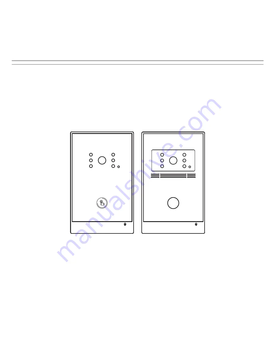
Page 4: ...Picture Model D C5 With glass surface Camera Call Button Speaker Infrared LEDs Microphone Light Sensor Model D C5 With metal surface Microphone Camera Call Button Infrared LEDs Light Sensor Speaker 1...
Page 5: ...sumption 2 5W 4 DDR2 1Gbit X 2 9 Flash 16Gbit Check the package content Technology Parameter 1 Call indoor monitor or management center 2 Video intercom with indoor monitor or management center 3 Supp...
Page 6: ...ill ring When it is set as help station press the call button the management center will ring Calling IP address View same LAN Install 700 Upgrade Tool in PC and press search button to view the IP add...
Page 7: ...terface 1 LAN setting Click LAN icon on the interface to enter into the following interface IP IP address should be unique in the same LAN Mask The default Mask is 255 255 255 0 Gateway It depends on...
Page 8: ...you need to distinguish their numbers from 1 to 9 Sys password You can change the login password as you like the default password is 123456 Panel mode unit panel wall panel and personal panel for opti...
Page 9: ...n for 0 9 seconds It is reserved Admin Card It is reserved Press Submit button to confirm settings 4 VOIP Click VOIP icon on the interface to enter into the following interface Input the relevant info...
Page 10: ...rm settings When the outdoor panel calls the indoor monitor it will transfer to IP phone and you can make communication with IP phone accordingly 2 Call management center Input the room No of outdoor...
Page 11: ...9 Logout Click Logout icon on the interface to enter into the following interface Click Submit icon to logout the system 8...
Page 12: ...NO NC NC GND GND V V 485 485 485 485 RVV4 0 5 Electric lock Reserved 485 data interface Optional 1 If you use the same power supply for outdoor panel and lock please find the system diagram as follow...
Page 13: ...Connect with magnetic lock CAT 5e GND GND V V 485 485 485 485 RVV4 0 5 Reserved 485 data interface 12V GND CTRL LOCK GND GND 12V Magnetic lock LOCK LOCK Power DC12V 10...
Page 14: ...rate power supply please find the system diagram as follows Optional 2 CAT 5e GND GND V V 485 485 485 485 RVV4 0 5 Reserved 485 data interface GND 12V Lock DC Power Supply 12V GND 18V CTRL LOCK1 LOCK2...
Page 15: ...Power on Ethernet Compatible with IEEE 802 3af 48V PoE standard GND 12V 12V GND 18V CTRL LOCK1 LOCK2 PoE Switch CAT 5e 12 Lock DC Power Supply NO COM NC Power DC12V optional...
Page 16: ...Build in box Hole l Drain hole Break through the cord hole on the bottom of the build in box firstly for water draining Please don t cover the drain hold with the glass cement 13 Installation...
Page 17: ...ot drop knock or shake the unit 3 Do not put the unit in hot areas If the temperature is too high it will shorten the using life of the unit 4 Do not use the wet dishcloth or volatile cleansers to cle...