INSTALLATION MANUAL
Model: Smart Analyzer®
Manufacturer: Smart Impulse
Power meter with consumption breakdown by use
03/12/13
Page 1: ...INSTALLATION MANUAL Model Smart Analyzer Manufacturer Smart Impulse Power meter with consumption breakdown by use 03 12 13...
Page 2: ...sentation 4 3 1 Box 4 4 Installation 5 4 1 Box set up 5 4 2 Sensors set up 6 4 3 Connection to the telecommunication network 7 4 4 Connection diagram 8 5 Commissioning 10 5 1 Switching on 10 5 2 Confi...
Page 3: ...carefully all the notes designated by this symbol 2 2 General installation precautions Read carefully this manual The facilities safety in which the Smart Analyzer is installed remains the responsibi...
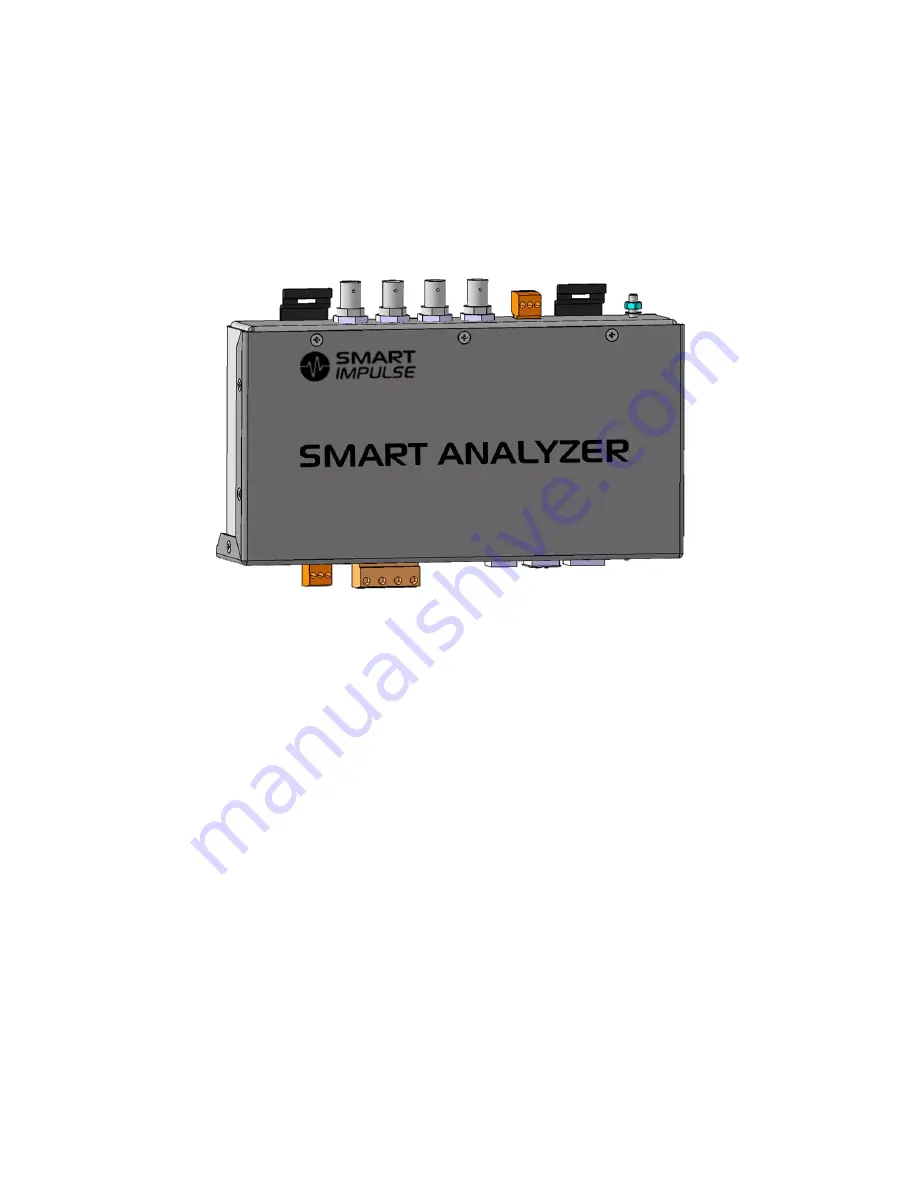
Page 4: ...ing clips on DIN rail 4 Ground connector screw M4 5 Smart Analyzer power connector From l to r N C Ground 24 V 6 Voltage measure connector From l to r Neutral Phase 1 Phase 2 Phase 3 7 USB device and...
Page 5: ...cascading and the selection of the sizes and breaking capacities 4 1 Box set up The Smart Analyzer has a DIN rail standardized fastening system Please respect the following indications 1 Set up a tet...
Page 6: ...on the dedicated terminal block 4 pins The neutral must be positioned on the far left The phase order may not be respected 4 Connect the terminal block to the Smart Analyzer The voltage metering input...
Page 7: ...a given phase the current sensor must link all these wires Note 3 For a single phased installation do not connect phases 2 and 3 4 3 Connection to the telecommunication network The Smart Analyzer must...
Page 8: ...Smart Analyzer PAGE 8 of 16 4 4 Connection diagram Note this diagram is not valid for IT neutral point connections...
Page 9: ...www smart impulse com Smarter Metering...
Page 10: ...n the local memory within the limit of the available space 48 hours approx 5 2 Configuration The device has a web administration interface that enables to set up certain parameters according to the in...
Page 11: ...factory Do not modify it except for maintenance operations For each current coil enter the model and serial number last line on the RT 2000 code with bars on the i430 Flex Click on Confirm once these...
Page 12: ...y III Pollution category 2 Rated voltage 300 VRMS Indoor use Electromagnetic compatibility cat A non industrial environment Conducted and radiated emissions according to EN 55011 2009 A1 2010 Near fie...
Page 13: ...ases neutral 253 VRMS Input impedance 52 k between phase and neutral Tolerable overload 275 VRMS in continuous by varistor Current inputs Operating range 0 1 V Input impedance 100 Tolerable overload 1...
Page 14: ...3 V m Relative humidity 10 to 90 without condensation 8 Maintenance No cleaning is required for the proper operation of the device If necessary use a dry cloth For any maintenance operation contact S...
Page 15: ...www smart impulse com Smarter Metering Notes...
Page 16: ...Smart Analyzer PAGE 16 of 16 SMART IMPULSE 48 rue Ren Clair 75018 PARIS 33 0 1 84 17 31 20 contact smart impulse com...