background image

Appendix D

79

Appendix D:

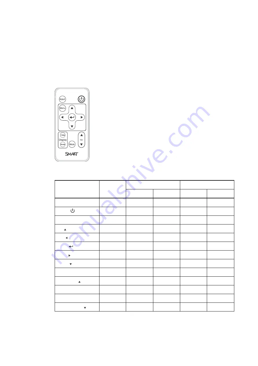
Remote control code definitions

IR signal format: NEC1

Key

Repeat
format

Vendor code

Key code

Byte 1

Byte 2

Byte 3

Byte 4

Input

F1

8B

CA

14

EB

Power ( )

F1

8B

CA

12

ED

Menu

F1

8B

CA

1B

E4

Up ( )

F1

8B

CA

40

BF

Left ( )

F1

8B

CA

42

BD

Enter (

)

F1

8B

CA

13

EC

Right ( )

F1

8B

CA

43

BC

Down ( )

F1

8B

CA

41

BE

Hide

F1

8B

CA

15

EA

Volume up ( )

F1

8B

CA

44

BB

Mode

F1

8B

CA

45

BA

Mute

F1

8B

CA

11

EE

Volume down ( )

F1

8B

CA

46

B9

Summary of Contents for M600i6

Page 1: ...SMART Board M600i6 Interactive whiteboard systems Configuration and user s guide For models M680i6 and M685i6...

Page 2: ...ART Notebook SMART Meeting Pro DViT smarttech the SMART logo and all SMART taglines are trade marks or registered trade marks of SMART Technologies ULC in the US and or other countries Microsoft Windo...

Page 3: ...ccessories and optional equipment The projector included with your system is designed to work only with certain SMART Board interactive whiteboard models Contact your authorised SMART reseller smartte...

Page 4: ...could cause a malfunction and shorten the life of the projector l Avoid setting up and using the SMART product in an area with excessive levels of dust humidity and smoke l Do not place your SMART pr...

Page 5: ...T Board M680i6 and M685i6 series interactive whiteboard system refer to the installation manual for your product for relevant warnings and maintenance instructions Environmental requirements Before yo...

Page 6: ...nformation on cleaning the projector Electrostatic discharge ESD l EN61000 4 2 severity level 4 for direct and indirect ESD l No malfunction or damage up to 8kV both polarities with a 330 ohm 150 pF p...

Page 7: ...taining your interactive whiteboard 21 Cleaning the projector 22 Focusing and adjusting the projector image 23 Replacing the projector lamp 23 Chapter 5 Troubleshooting your interactive whiteboard sys...

Page 8: ...emote control code definitions 79 Appendix E Hardware environmental compliance 81 Waste Electrical and Electronic Equipment and Battery regulations WEEE and Battery Directives 81 Batteries 81 Mercury...

Page 9: ...ies 4 Remote control 4 Pens 4 Optional accessories 4 Your SMART Board M600i6 interactive whiteboard system combines the following components l SMART Board M600 series interactive whiteboard l Wall mou...

Page 10: ...within applications This projector also supports video and audio connections from a variety of devices including DVD Blu ray players VCRs document cameras and digital cameras and can project media fr...

Page 11: ...ts providing BrilliantColor performance and Gamma 2 2 correction with SMART Presentation Bright Room Dark Room sRGB and User modes l PAL PAL N PAL M SECAM NTSC and NTSC 4 43 video system compatibility...

Page 12: ...and input selection options Pens There are two pens included with your interactive whiteboard Pick up a pen and press one of the four colour buttons on the pen tray black red green or blue to select...

Page 13: ...ng Bright light sources can cause distracting shadows on your interactive whiteboard and can reduce the contrast of the projected image Select a wall with a flat regular surface and sufficient clearan...

Page 14: ...ght of your user community when you choose a location for your interactive whiteboard Securing the projector to the boom To learn how to secure the SMART UF70 or SMART UF70w projector to the boom see...

Page 15: ...borative learning software on the computer connected to your interactive whiteboard system to access all of its features Download SMART software from smarttech com software These webpages list the min...

Page 16: ......

Page 17: ...oard 20 This chapter describes the basic operation of your interactive whiteboard system and explains how to set up your remote control retrieve system information access the projector s image adjustm...

Page 18: ...rge the battery or expose it to fire or high temperatures o Avoid eye and skin contact with the battery if it has a leak l Dispose of the exhausted battery and product components in accordance with ap...

Page 19: ...ciated USB input source on the ECP if present 2 Menu Show or hide the projector menus 3 Left Right Up and Down arrows Change the menu selections and adjustments 4 Hide Freeze hide or display the image...

Page 20: ...usts projector brightness from 0 to 100 The default is 50 Contrast Adjusts the difference between the lightest and darkest parts of the image from 0 to 100 The default is 50 Frequency Adjusts the disp...

Page 21: ...of the display from 1 to 3 The default is 2 Colour Adjusts the Red Green Blue Cyan Magenta and Yellow colours on the projector from 0 to 100 to provide custom colour and luminance output Each colour h...

Page 22: ...e zoom to the centre of the image in or out from 0 to 30 The default is 0 Zooming in cuts off the outer edges of the source video Keystone Adjusts the size of the top and bottom edge Ensure that the t...

Page 23: ...n enables you to adjust the projected image size shape and location Image Alignment Screen Enables you to adjust the projected image size shape and location The image alignment screen appears the firs...

Page 24: ...e projector s MAC address in xx xx xx xx xx xx format Group Name Displays the projector s workgroup name as set by an administrator maximum 12 characters You can set the projector s workgroup name usi...

Page 25: ...ace a lamp because lamp service reminders are based on the current hours of use See Resetting the lamp hours on page 27 for details on the lamp hours reset procedure Input Displays the currently displ...

Page 26: ...cation l Use the mechanical adjustments described in the installation document to make all physical image adjustments Don t use the projector s on screen menu options during the projector alignment pr...

Page 27: ...Power Mains power supply 2 7 pin mini DIN Not used 3 4 pin power mini DIN 5V 2A output Not used 4 HDMI input High definition video and audio source not included 5 DB15F DE 15F RGB video input VGA 1 P...

Page 28: ...m kb 170410 for in depth information on using your interactive whiteboard and its features When you connect your SMART Board interactive whiteboard to a computer with SMART software you can access the...

Page 29: ...rd see the SMART Board M600 interactive whiteboard installation guide smarttech com kb 170555 With proper care your SMART Board interactive whiteboard will provide years of trouble free service Preven...

Page 30: ...lamp off mode Cleaning the projector W A R N I N G Cleaning a wall mounted projector can result in a fall or injury Use caution when climbing a ladder and consider removing the projector from its wal...

Page 31: ...aning the projector s lens l Use a bellows bulb or air blower bulb commonly found in audio visual supply stores to blow off dust Never touch the lens with your bare hands or a brush l If wiping the le...

Page 32: ...om the wall mounting bracket to replace the lamp module l Uncovering the lamp whilst the projector is mounted on the wall mounting bracket can lead to product damage or personal injury from falling pi...

Page 33: ...at least 30 minutes for the projector to cool down 3 Disconnect the power cable from the projector 4 Use a Phillips screwdriver to loosen the two captive screws Lamp Door 5 Use a Phillips screwdriver...

Page 34: ...O R T A N T Do not over tighten the screws 4 Replace the lamp cover 5 Connect the power cable to the wall socket 6 Press the Power button once on the remote control to confirm that the projector is o...

Page 35: ...T I O N Do not adjust any settings in the service menu other than those listed in this guide Changing other settings can damage or affect the operation of your projector and may invalidate your warra...

Page 36: ......

Page 37: ...lour Wheel Failure message appears 33 The Lamp Failure message appears 34 The projector Power and Service lights are off 34 Resolving image issues 34 Loss of signal 35 Partial scrolling or incorrectly...

Page 38: ...interactive whiteboard system s status lights l Locate your interactive whiteboard system s serial numbers Locating status lights Your interactive whiteboard system consists of several components whi...

Page 39: ...age or sound issues occur see the remaining sections of this chapter for troubleshooting information Flashing green Off Off None None The system is starting up Solid amber Off Off None None The system...

Page 40: ...ilure Lamp Failure or Colour Wheel Failure message appears on the next page Off Off Off None None The projector power cable isn t properly connected OR There s an issue with the mains power supply for...

Page 41: ...ailure or Colour Wheel Failure message appears If the Projector Overheated Fan Failure or Colour Wheel Failure message appears and the projector stops projecting an image one of the following issues i...

Page 42: ...power cable and then contact your authorised SMART reseller The projector Power and Service lights are off If the projector Power and Service lights are both off one of the following issues is occurri...

Page 43: ...ise Some video signals require a longer synchronisation period Cycling back through inputs to the one that you want also helps image synchronisation 2 If the image doesn t synchronise check your cable...

Page 44: ...ickering image If the projector s image is unstable or flickering the frequency or tracking settings on your input source could be different from the settings on your projector I M P O R T A N T Write...

Page 45: ...et the aspect ratio mode using the Native DLP Resolution setting in the Projector Functions menu see Adjusting projector settings on page 12 The image from your connected laptop computer isn t project...

Page 46: ...d up 5 Check that your source input such as your computer or video device isn t malfunctioning Ensure that its audio output is on and that the volume isn t set to the lowest position N O T E You must...

Page 47: ...users of your interactive whiteboard system l Do not adjust any settings in the service menu other than those listed in this guide Changing other settings can damage or affect the operation of your pr...

Page 48: ...hiteboard system Save your original interactive whiteboard system packaging so that it s available if you need to transport your interactive whiteboard system When required repack it with all of the o...

Page 49: ...tructions on how to remotely manage your SMART Board M600i6 interactive whiteboard system settings through a network interface Webpage management You can access advanced setup features via the project...

Page 50: ...e menu page displays basic projector information and enables you to select the on screen display language N O T E You can view basic projector information but you re unable to change it with the excep...

Page 51: ...ector brightness from 0 to 100 Contrast Adjusts the difference between the lightest and darkest parts of the image from 0 to 100 Frequency Adjusts the display data frequency of the projected image fro...

Page 52: ...video up or down from 5 to 5 relative to the projected image N O T E This is useful in situations where the source video is cut off Aspect Ratio Adjusts the image output to Fill Screen Match Input or...

Page 53: ...Assigns an alternative name to your HDMI input which appears when you select the HDMI input Emergency Alert Turns the on screen alert broadcast message on or off When enabled this message displays ov...

Page 54: ...r off Read Only Community Sets a password that is required for each SNMP get request to the device N O T E The default for Read Only Community is public Read Write Community Sets a password that is re...

Page 55: ...ur email address Click Email Alert Test to confirm that your email address and SMTP server settings are correct by sending a test email SMART Alert Test Mail If the settings aren t correct the email a...

Page 56: ...n the management information base MIB file You can download this file by browsing to smarttech com software and clicking the MIB file s link in the Hardware section for the SMART UF70 projector The SN...

Page 57: ...response definitions 61 Field definitions 62 System information 62 Command response definitions 62 Field definitions 65 Service Information 69 Command response definitions 69 Field definitions 70 Unk...

Page 58: ...nication settings with the following values Setting Value Data Rate 19 2 kbps Data Bits 8 Parity None Stop Bits 1 Flow Control None N O T E S l Asynchronous mode is disabled by default in the projecto...

Page 59: ...configure your settings N O T E S o To see a list of commands available in the current operating mode type and then press ENTER o If you re using a terminal emulation program turn on your program s lo...

Page 60: ...projector has turned off this command should be accepted but doesn t do anything but return the power state powerstate l powering l on l cooling l confirm off l idle The projector s current power stat...

Page 61: ...ned in this command must match the strings used for the input selection from the on screen display OSD VGA1 and HDMI1 are local at the projector VGA2 and HDMI2 are at the UCP The maximum could be 10 i...

Page 62: ...ly A change should be made to ensure that videofreeze and videomute are mutually exclusive Command response definitions Command Response Responds when powered off set displaymode target displaymode cu...

Page 63: ...ent no set degamma target degamma current no get degamma degamma current no set red target red current no get red red current no set green target green current no get green green current no set blue t...

Page 64: ...tness target contrast l val l val l 0 to 100 Use or to change the contrast incrementally Enter a number within the range to set the contrast to a specific level current contrast Range 0 to 100 The dev...

Page 65: ...l val l 0 to 10 The ranges must match the OSD ranges current whitepeaking Range 0 to 10 The ranges must match the OSD ranges target degamma l val l val l 0 to 3 The ranges must match the OSD ranges cu...

Page 66: ...ent videofreeze l on l off Video freeze on off current displayhide l normal l frozen l muted Matches the three states of the Hide button on the remote control target displayhide l normal l frozen l mu...

Page 67: ...controls The range of values used for these commands should match the range shown in the on screen display OSD Command response definitions Command Response Powered off set volume target volume curren...

Page 68: ...hould map to 0 and 20 should map to 40 target mute l on l off Specifies whether mute is enabled or disabled current mute l on l off Current state of the mute function current volumecontrol l on l off...

Page 69: ...status netstatus current yes set network network current yes get network network current yes set dhcp target dhcp current yes get dhcp dhcp current yes set ipaddr target ipaddr current yes get ipaddr...

Page 70: ...nt IP address static or dhcp assigned target ipaddr Range 0 0 0 0 to 255 255 255 255 Set to static IP Address current subnetmask Range 0 0 0 0 to 255 255 255 255 Current subnet Mask target subnetmask...

Page 71: ...get autopoweroff set zoom target autopoweroff current no set zoom target zoom current no get zoom zoom current no set projectorid target projectorid current no get projectorid projectorid current no s...

Page 72: ...language language current no set groupname target groupname current no get groupname groupname current no set projectorname target projectorname current no get projectorname projectorname current no s...

Page 73: ...ption target autosignal l on l off The ranges must match the OSD settings current autosignal l on l off The ranges must match the OSD settings target lampreminder l on l off The ranges must match the...

Page 74: ...ge on an XGA projector and as a 16 10 image on a WXGA projector Match The signal is scaled so that the input aspect ratio is maintained For example a 4 3 image appears as a 4 3 image on screen 16 9 Th...

Page 75: ...800x600 l 1024x768 l l no signal Current resolution of the input If no signal is detected resolution no signal appears native aspect ratio 4 3 for SMART UF70 16 10 for SMART UF70w Native aspect ratio...

Page 76: ...e l Korean l Norwegian Norsk l Polish l Portuguese Brazil l Portuguese Portugal l Russian l Spanish l Swedish Must match the OSD setting target language above Must match the OSD setting target groupna...

Page 77: ...on l off To display the alert message set this value to on target emergencyalertmsg l on l off If the message is being displayed on is returned current signaldetected l true l false If a signal is de...

Page 78: ...poweroverride poweroverride current no set poweroverride target poweroverride current no Field definitions Field Possible Values Description current displayhour 0 to 20000 Current display hours target...

Page 79: ...5 indicates the oldest error The details include the failure reason system hours lamp hours sensor temperature and lamp voltage Example error1 fansystem syshrs 1000 lamphrs 1000 temp 60 volt 120 error...

Page 80: ...e memory cleared on power cycle When this mode is enabled the power button on the remote control and the ECP if present must not turn off the projector This command must also be added to the service m...

Page 81: ...m with peripheral devices Video format Your projector has a native video format and various video format compatibility modes You can change image appearances for certain formats and compatibilities Na...

Page 82: ...60 4 3 60 004 Full screen 1024 768 XGA 70 4 3 70 069 Full screen 1024 768 XGA 75 4 3 75 029 Full screen 1024 768 XGA 85 4 3 84 997 Full screen 1024 768 MAC 19 4 3 74 7 Full screen 1152 864 SXGA1 75 4...

Page 83: ...box Pillarbox 800 600 SVGA 75 4 3 75 Pillarbox Pillarbox 800 600 SVGA 85 4 3 85 061 Pillarbox Pillarbox 832 624 MAC 16 4 3 74 55 Pillarbox Pillarbox 1024 768 XGA 60 4 3 60 004 Pillarbox Pillarbox 1024...

Page 84: ...format Aspect ratio Horizontal frequency kHz Vertical frequency Hz Match Input appearance 16 10 aspect ratio mode Match Input appearance 16 9 aspect ratio mode 480i 525i 4 3 15 73 59 94 Pillarbox Pil...

Page 85: ...tio Horizontal frequency kHz Vertical frequency Hz Colour signal MHz NTSC 4 3 15 73 29 96 3 58 PAL 4 3 15 62 25 4 43 SECAM 4 3 15 62 25 4 25 fob 4 06 for SMART UF70w projector Video mode Aspect ratio...

Page 86: ...devices 78 To connect a peripheral source or output to your projector 1 Connect your peripheral device s input cables to the projector 2 Switch input sources to the peripheral device by pressing the...

Page 87: ...de Byte 1 Byte 2 Byte 3 Byte 4 Input F1 8B CA 14 EB Power F1 8B CA 12 ED Menu F1 8B CA 1B E4 Up F1 8B CA 40 BF Left F1 8B CA 42 BD Enter F1 8B CA 13 EC Right F1 8B CA 43 BC Down F1 8B CA 41 BE Hide F1...

Page 88: ......

Page 89: ...to the environment and to human health The crossed out wheeled bin symbol indicates that products should be disposed of in the appropriate recycling stream and not as regular waste Batteries Remote co...

Page 90: ......

Page 91: ...CP 15 45 display modes 11 12 43 DNS 46 document cameras 77 dust iv DVD players 77 E electrostatic discharge iv email alerts 46 emergency alerts 45 emissions iv environmental requirements iii F fans 33...

Page 92: ...the name of 46 focusing the image of 18 installing 5 lights and status of 30 locating the serial number on 30 remotely managing 41 49 replacing the lamp of 23 routing cables from 6 securing to the boo...

Page 93: ...or UF70w projector See projector USB ports 19 UXGA support 73 74 V VGA connections 19 45 VGA support 73 74 video connections for 19 format compatibility for 73 W warnings ii water and fluid resistance...

Page 94: ......

Page 95: ......

Page 96: ...Undefined variable SMARTTrade marks Company_Long smarttech com support smarttech com contactsupport...

Reviews: