background image

Chapter 6. Options Page

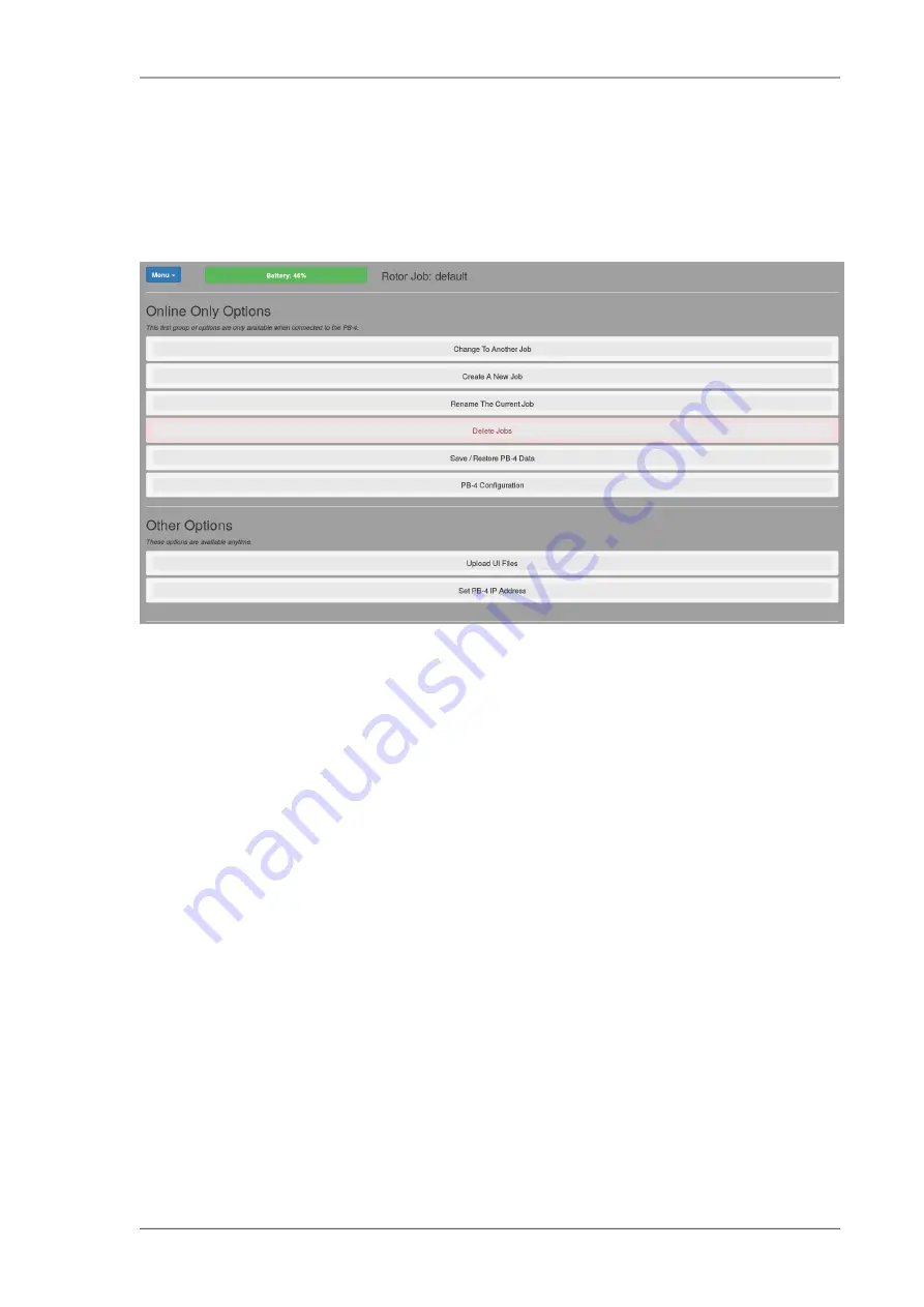
The options page contains large buttons that, when clicked, expand the

selected section to show the controls for that option. Most of the options are

only available when the user interface is connected to the PB-4.

Fig 6.1. Options page (when connected to PB-4)

6.1. Change to another job

The section expands to show a list of jobs known to the PB-4, click on one to

load it into the browser so it becomes the current job.

6.2. Create a new job

The section expands to show 3 controls:

• A text input box into which you enter the name of the new job - it must not

be the same as an existing job name.

• A drop-down list of existing job names - if you select one, the new job will

be a copy of the selected job. This provides an easy means to create a new

job with a similar configuration to an existing job.

• A Create Job button that creates the job and loads it into the browser.

37

www.smartavionics.com

Summary of Contents for PB-4

Page 1: ...PB 4 Propeller Rotor Balancer User Interface Manual Smart Avionics Ltd 17 07 2019 www smartavionics com Revision 2 4...

Page 2: ...r Balancer User Interface Manual Revision 2 4 Publication date 17 07 2019 Copyright 2003 2019 Smart Avionics Ltd Android is a trademark of Google Inc iOS is a trademark of Apple Inc Dropbox is a trade...

Page 3: ...1 Polar chart 15 3 1 1 Capture button 16 3 2 Points list 17 3 3 Option buttons 18 3 3 1 Print Polar Chart menu 18 3 3 2 What Next button 18 3 3 3 Show Waveform button 19 3 3 4 Polar Options button 19...

Page 4: ...wrong 48 7 8 2 The current polar point position varies widely 48 7 8 3 Adding weight does not reduce the vibration level 49 8 Rotor Balancing 51 8 1 Causes of rotor vibration 51 8 2 Rotor adjustments...

Page 5: ...on top view 21 3 7 Point details dialog rotor mode 22 3 8 Rotor balance solution dialog 23 3 9 Edit move line dialog 24 3 10 Span Adjustment Settings 26 4 1 Spectrum tab with options visible 29 4 2 Ro...

Page 6: ...www smartavionics com vi...

Page 7: ...and the tablet to be using the same Wi Fi network 1 1 1 Accessing the PB 4 user interface AP mode When the PB 4 is in AP mode the Wi Fi network name SSID will be PB4 XX where XX are two letters digit...

Page 8: ...e start it in AP mode press on off only until LED 1 comes on 4 Access the PB 4 user interface page with your browser as described in the previous section connect to the PB 4 click on red button and th...

Page 9: ...screen It should be usable on many different user interface devices For in cockpit use a 7 form factor tablet is ideal For lower resolution devices you may find that changing the orientation to lands...

Page 10: ...ther click Menu Fullscreen again or press the Esc key if your device has a keyboard Help Clicking this will display a simple web page with links to the PB 4 documentation About Clicking this will disp...

Page 11: ...ing since the batteries were last changed It assumes the batteries were fully charged to their rated capacity when they were installed b This low battery warning is based on the battery voltage and is...

Page 12: ...www smartavionics com 6...

Page 13: ...cked the chart will be updated in real time to show the current balance condition The current point is simply the most recent point sent from the PB 4 when the display is being updated in real time or...

Page 14: ...box is only visible if there is a start point defined for the axis It shows a solution i e what adjustment needs to be made to the balance weight to improve the balance The adjustment has the form ANG...

Page 15: ...chart The choices are All All points will be displayed Also the point index number column is highlighted and clicking on a point s index number will toggle its hidden state Visible All points that hav...

Page 16: ...weights that were present when that point was captured and the point s notes Groups of points with similar capture times and RPM values are separated by a black line Clicking on a row will make the s...

Page 17: ...ons that balance weights may be attached to For a typical propeller balancing job this would be the number of fasteners that hold the spinner to its backplate It cannot be less than 3 The PSRU Ratio t...

Page 18: ...makes the current point no longer to be considered the start point If the point was captured with acceleration data see the With Waveform Data option in Chapter 5 the Show Hide Waveform button will b...

Page 19: ...ed in the point details dialog Below the weight configuration are instructions as to how the current weight configuration should be changed to improve the balance The new weight amounts displayed are...

Page 20: ...www smartavionics com 14...

Page 21: ...balance condition The chart may show move lines the red green and blue lines in the above figure The current point is simply the most recent point sent from the PB 4 when the display is being updated...

Page 22: ...point s rotor RPM The top right box contains the accelerometer channel name X Y X2 or Y2 and the current point s IPS and DEG values The bottom right box contains the date time the current point was m...

Page 23: ...played Also the point index number column is highlighted and clicking on a point s index number will toggle its hidden state Visible All points that have not been hidden will be displayed Best Only th...

Page 24: ...e rows that correspond to axis 2 have a grey background Groups of points with similar capture times and RPM values are separated by a black line Clicking on a row will make the selected point the curr...

Page 25: ...oints but will make the display slower to react to input changes so you will need to wait longer for the point to settle in the averaged position The value should be between 1 and 50 the default is 15...

Page 26: ...tion this angle will be 0 Having a non zero tacho offset will rotate all the points around the centre of the chart in an anti clockwise direction If a second accelerometer is mounted near the front of...

Page 27: ...ation for the selected point along with some text input boxes and buttons as shown in Fig 3 7 To open this dialog simply click the selected point s row in the point list a second time The buttons are...

Page 28: ...he Notes text input box is used to enter any notes that you wish to record for the point Span adjustment Chord adjustment and Pitch adjustment input boxes may be used to update the adjustment values a...

Page 29: ...1 unit The dialog also shows the absolute state of the rotor after the suggested changes have been applied The dialog shows how the polar points should move when the changes in the solution have been...

Page 30: ...fined by the positions of two nodes which are specified in this dialog along with their adjustment values Each node has a position given as Deg and IPS and a value The nodes are drawn as filled circle...

Page 31: ...tiple of this value So if you are using washers for the units Step of adjustment and you only have washers of one size then a step of 1 would be appropriate but if you also had some washers that weigh...

Page 32: ...sensible default settings You may however alter these settings if you wish To do so click on the appropriate adjustment in the polar point list header and in the dialog that pops up click Show Adjust...

Page 33: ...t that is to be used Very small steps will increase the time taken to calculate the result Min Value Max Value These optional values specify lower and upper limits for the adjustment The balance solut...

Page 34: ...www smartavionics com 28...

Page 35: ...frequency blade pass frequency 3 engine crank and half crank frequencies etc Here we see the spectrum tab displaying a previously captured spectrum Fig 4 1 Spectrum tab with options visible The spect...

Page 36: ...the spectrum around that RPM is displayed in red and if any line labels have been defined they will be displayed in a box above their respective lines Line labels x1 and x2 are shown in the figures Th...

Page 37: ...y the PB 4 when it is connected If not checked the last displayed data is preserved So if you want to pause the display un check this checkbox The Show All checkbox decides whether hidden spectra are...

Page 38: ...e in your browser showing the currently selected spectrum and some textual information If the currently selected spectrum shows line labels a list detailing the line labels will be included You can th...

Page 39: ...ow type and later display it with another window type The Line Labels checkbox enables the display of line labels Line labels are simply short labels that are displayed above the line they refer to Th...

Page 40: ...www smartavionics com 34...

Page 41: ...capture checkboxes are enabled The Update checkbox controls whether the data display is automatically updated to show the latest data returned by the PB 4 when it is connected If not checked the last...

Page 42: ...is clicked It also controls whether spectra will be captured when the PB 4 s offline capture button is pressed The Enable PB 4 Offline Capture checkbox enables the PB 4 s hardware capture button that...

Page 43: ...n to the PB 4 click on one to load it into the browser so it becomes the current job 6 2 Create a new job The section expands to show 3 controls A text input box into which you enter the name of the n...

Page 44: ...your computer The second sub section contains a selector that lets you choose which jobs you wish to delete and a button to carry out the action which you will be asked to confirm Once confirmed all d...

Page 45: ...the PB 4 detects that they have been changed and resets the battery level to 100 If it fails to detect the changed batteries pressing the New Batteries Installed button will reset the battery level to...

Page 46: ...appears telling you what to do It s very easy Earth s Surface Sky Applying positive G to sensor s X axis Applying negative G to sensor s X axis Fig 6 2 Accelerometer orientation during calibration 6 6...

Page 47: ...aining the new PB 4 Wi Fi firmware you wish to install Select the required file and the contents will be uploaded to the PB 4 and installed Please see the PB 4 hardware manual for more information reg...

Page 48: ...ing of the UI web page 6 8 Set PB 4 IP address This section expands to show a text input box into which you can enter the IP address network address that will be used to connect the browser to the PB...

Page 49: ...d by mass balancing Important Before attempting to dynamically balance a variable pitch propeller either ground adjustable or in flight adjustable confirm that the blades pitch are equal to within the...

Page 50: ...accelerometer is securely attached to the engine as close to the propeller as possible and it measures the acceleration of the front of the engine in one direction normal to the propeller shaft If the...

Page 51: ...hed off before touching the propeller Always assume that the engine could fire when the propeller is being moved Make sure that the aircraft is securely chocked or tied down while carrying out the bal...

Page 52: ...out 0 03 IPS so you may wish to continue the process to achieve a better result If you want to improve the balance you must carry out the balancing procedure as described in the next section Tip To re...

Page 53: ...eight attached at a single location the trial weight so in one row enter the amount e g 3 for 3 washers and the location e g 1 An amount of zero means that no weight was attached 3 With the trial weig...

Page 54: ...M is erratic or wrong The RPM could be unsteady for the following reasons most likely first The optical sensor is not pointing at the reflective tape or the tape is not parallel with the sensor s bloc...

Page 55: ...s pistons You are using the wrong accelerometer axis The spinner is wobbling The engine cowling is not fitted to minimise the effects of turbulence 7 8 3 Adding weight does not reduce the vibration le...

Page 56: ...www smartavionics com 50...

Page 57: ...th description of how to use the PB 4 to balance a rotor is available from the Smart Avionics website 8 1 Causes of rotor vibration Mass imbalance is one of the causes of rotor vibration and the PB 4...

Page 58: ...irection tip to tip is commonly altered by adjusting the amount of weight that is attached to the Spanwise Balance tips of the rotor blades One of the blades is designated as the master blade the othe...

Page 59: ...es making the tips fly at the same height Here we do pitch adjustments along with mass adjustments in a combined balancing tracking operation that we simply refer to as balancing Fig 8 2 Rotor Adjustm...

Page 60: ...nts for two different values of each adjustment For example to define the spanwise move line you need to add weight to one of the rotor blade tips enter the adjustment value as described in Section 3...

Page 61: ...ally be copied across from the selected points That s it close the dialog You will need to create a move line for each axis X and Y and each adjustment span chord and possibly pitch So you should end...

Page 62: ...www smartavionics com 56...

Page 63: ...o plane balancing method is really very similar to the single plane balancing method It involves measuring the vibration when no trial mass is attached measuring the vibration with trial mass attached...

Page 64: ...the 1 correction plane but the 2 measurement plane is far from the 2 correction plane MEASURING PLANES 1 2 CORRECTION PLANES 1 2 Fig 9 2 Two plane balancing an overhung object 9 2 Two plane balancing...

Page 65: ...that is 50 backwards against the direction of rotation from the position where the plane 1 trial mass was attached The plane 2 solution is 82 1 14 which says attach a mass that is 1 14 times the tria...

Page 66: ...nfigurations to provide the data for the 3 points on the right hand side of the dialog It is important that when you attach the trial mass you use the same positions as you did previously It is also i...

Page 67: ...on plane 2 and capture a couple of points Mark the position of the mass and remove it You now have all 6 points required Take care to select the correct points when entering the data into the view 61...

Page 68: ...www smartavionics com 62...

Page 69: ...per g 2 382 accel adc counts per g 3 255 balancer cycles 4 balancer min cycles 15 balancer max points to average 0 balancer polar mode Hann 1 fft window type 50 fft rpm per line seconds 30 idle timeou...

Page 70: ...www smartavionics com 64...

Page 71: ...buttons File Cancel and Save The File button pops up a menu containing these items Export Configuration Prompts the user for the name of a file to save the UI configuration data into JSON format All...

Page 72: ...profiles B 1 Editing rotor profiles Clicking on a rotor profile name expands the section to show the profile values If the profile is predefined but not None or Standard the values can be edited and t...

Page 73: ...d have a browse through the values to see what can be configured If you change something and later decide you want the original value back just use the individual reset button Remember that changes to...

Page 74: ...www smartavionics com 68...

Page 75: ...petal force 43 44 configuration values accessing 40 connect button 4 correction planes 57 current point 7 15 D data options 35 data tab 35 delete multiple jobs 38 E edit move line button 19 dialog 24...

Page 76: ...ctrum display 32 responsive user interface 3 rotor balance calculate solution 22 recalculate solution 23 rotor profile 66 RPM choice 45 erratic 48 per spectral line 32 S save restore data 38 sensorOff...

Page 77: ...button 10 18 Wi Fi AP mode 1 STA mode 1 wind 49 with waveform data checkbox 36 71 www smartavionics com...

Page 78: ...www smartavionics com 72...

Reviews: