Electrical Connection
SMA America, LLC
36
SB50US-80US-eng-IUS112633
Installation Guide
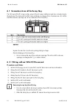
6.1 Connection Area of the Sunny Boy
The DC input of the PV array and the output of the AC power distribution grid are connected inside
the enclosure. The internal AC and DC terminal blocks are designed for a maximum size of 6 AWG.
Suitable enclosure openings are on the underside of the Sunny Boy.
6.1.1 Wiring without SMA DC Disconnect
Procedure and Order
1. Switch off all energy sources. Open all AC and DC disconnect switches and breakers.
2. Wiring from AC breaker to the AC disconnect switch.
3. Wiring from AC disconnect switch to the Sunny Boy.
4. Wiring from the PV lines to the DC Disconnect.
5. Wiring from the DC disconnect switch to the Sunny Boy.
6. Switch on DC switch and breaker.
7. Switch on AC switch and breaker.
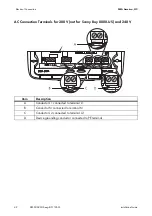
Item
Description
A
1
⁄
2
in. screws for communication cable with filler-plugs
B
3
⁄
4
in. DC opening with double membrane adapter
C
3
⁄
4
in. AC opening with double membrane adapter
NOTICE
Ingress of water due to enclosure openings being too large.
Potential damage to the Sunny Boy.
• Do not increase the size of the enclosure openings. The AC and DC enclosure
openings are designed for
3
⁄
4
in. cable conduits.
Removing Sunny Boy from Wiring
• First, disconnect all AC disconnect switches, then all DC disconnect switches.
Disconnect the AC side from the DC side.
• When the Sunny Boy is switched off, remove the wiring in reverse order.


