6 Connection
SMA Solar Technology AG
Installation Manual
29
EDMM-WAGO-IO-IA-en-11
6.5.5
Connecting different components at the I/O modules
Five I/O modules are available for connecting different components:
• 8-channel DC 24 V digital input terminal
• 8-channel DC 24 V digital output terminal
• 2/4-channel analog input terminal 2 TempIN (PT100)
• 4-channel analog input terminal 4 mA to 20 mA
• 4-channel analog output terminal 0 mA to 20 mA
6.5.5.1
8-channel DC 24 V digital input terminal
The 8-channel DC 24 V digital input terminal is comprised of binary control signals from the field area (e.g. from
sensors, transmitters, switches or proximity switches).
The bus terminal has 8 input channels and allows for direct connection of sensors with 2-conductor technology
(potential-free contact). The sensors are connected to the CAGE CLAMP® connections DI 1 and 24 V to DI8 and
24 V.
For interference suppression, each input channel is equipped with an RC filter with a time constant of 3.0 ms. The
inputs of the us terminal are positive switching. If the 24 V potential for the field supply is switched on an input
connection, the signal state of the corresponding input channel is “high”. Green status LEDs indicate the respective
signal state per channel.
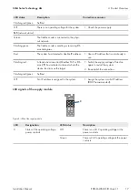
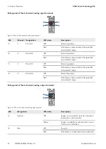
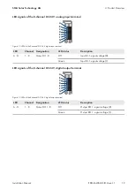
For detailed information on evaluation of the LED statuses (see Section 4.8 "LED Signals", page 16).
A
B
C
D
E
F
G
H
I
J
K
L
M
N
O
P
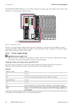
Figure 17: Connections of the 8-channel DC 24 V digital input terminal
Position
Channel Connec-
tion
Designation
Designation
A - H
1 - 8
1 - 8
DI 1- 8
Digital input 1 - 8: signal voltage
I - P
9 - 16
24 V
Digital input 1 - 8: sensor 24 V
Summary of Contents for Modbus EDMM-10
Page 54: ...www SMA Solar com...


