5 Mounting
SMA Solar Technology AG
Installation Manual
EDMM-WAGO-IO-IA-en-11
22
5
Mounting
5.1
Requirements for Mounting
NOTICE
Errors due to changed installation sequence
The sequence of the I/O modules is fixed. Changing the sequence can impact the function of the product and
cause errors.
• Do not change the sequence of the I/O modules.
Permitted and prohibited mounting positions:
In addition to horizontal and vertical mounting, all other mounting positions are allowed.
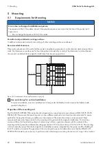
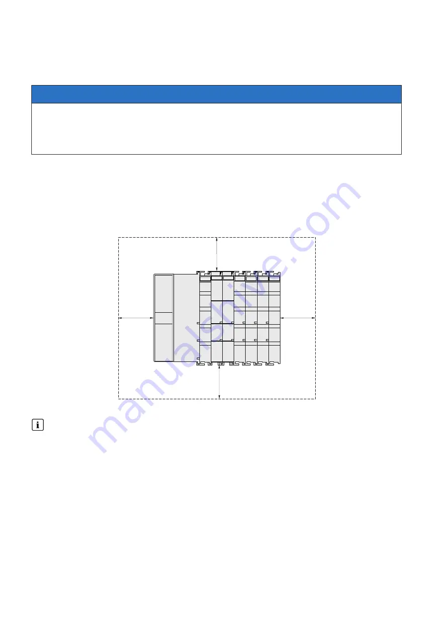
Recommended clearances:
Observe the clearances of the entire fieldbus node to neighboring components, cable channels and enclosure/frame
walls. The clearances provide space for heat dissipation and assembly or wiring. The clearances to cable channels
also prevent conducted electromagnetic interference from impacting operation.
35 (1.37)
35 (1.37)
35 (1.37)
35 (1.37)
Figure 14: Recommended clearances(Dimensions in mm (in))
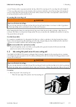
Use end clamps for vertical installation
For vertical installation, mount an additional end clamp under the fieldbus node to secure the fieldbus node
against sliding down.
Properties of the mounting rail
The WAGO-I/O-SYSTEM 750 can be directly snapped onto a mounting rail in accordance with EN 60175 (TS 35,
DIN Rail 35). Please note that mounting rails can have different mechanical and electrical characteristics. To ensure
optimal functioning, the following conditions must be observed: The material must be corrosion-resistant. Most
components have a discharge contact to the mounting rail to ground electromagnetic interference. To avoid any
corrosive effects, this tin-plated mounting rail contact may not form a galvanic element with the material of the
mounting rail that generates a differential voltage greater than 0.5 V (saline solution of 0.3% at 20°C). The mounting
rail must optimally support the electromagnetic compatibility measures integrated into the system and the shielding of
the I/O module connections. The geometry of the mounting rail may not be altered to ensure that the WAGO-I/O-
SYSTEM 750 is held in place security. In particular, when shortening or mounting the carrier rail, it may not be crushed
Summary of Contents for Modbus EDMM-10
Page 54: ...www SMA Solar com...


