background image

5. POWER

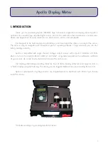
Apollo is powered by a 9V PP3 battery, fitted into a compartment on the back of the meter. One PP3 

alkaline battery is shipped with Apollo. Please make sure to insert the battery in the correct orientation (take 
notice of the + and — shown on the battery and inside the case.) No damage to Apollo will occur if it is 
inserted incorrectly by accident.

A battery is expected to last approximately 24 hours of continuous use at normal working conditions 

(~20

o

C), although this may be less if using amplified sensors that require a voltage input. Rechargeable 

batteries may be used if preferred, although they will usually not last as long as "normal" batteries, and will 
need recharging more often.

It is possible, and recommended, to check the battery status from the main menu frequently - at least 

prior to every use, and if Apollo is used for long periods of time, then perhaps every 2-3 hours. The menu  
option shows an actual reading of battery Voltage, as well as a meaningful "status", e.g. good (at >8.1V), 
medium (6.9 - 8.1V), low (6.0 - 6.9V) battery. If it is below 6.0V, then a message will apear prompting a battery 
change. Apollo's readings will remain accurate until the LCD display fades. These values are based on an 
alkaline battery being used.

Apollo has an AutoOff function to save battery life. Please see Section 4.6 for more information.

6. SENSOR CONNECTION

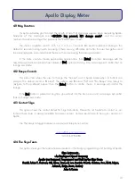
Apollo has a 5-pin Binder female socket. All Apollo-compatible Skye sensors are fitted with a matching 

plug. To attach a Skye light sensor to Apollo match up the sensor plug to the socket and align the locating 
pin. Push together and screw up gently finger tight. This type of connection is waterproof, however the Apollo 
meter itself is only splashproof.

The Apollo meter is compatible with single channel voltage output sensors. Skye sensors are wired 

thus, but please see individual sensor manual(s) for more information.        

Apollo can be configured to work with various 1 channel sensor 
types. The following describe the connection modes that can be 
changed in the "Wr Sensr Setup" menu. More information can be 
found in Appendix 2.

Mode 3

 = Differential Floating

Mode 4

 = Differential Grounded

Mode 5

 = Differential (2.5V referenced)

11

Apollo Display Meter

Pin #

Function

Pin 1

+5V Output

Pin 2

Not Connected

Pin 3

–'ve Voltage Input

Pin 4

+'ve Voltage Input

Pin 5

Analog/ Supply Ground.

Summary of Contents for APOLLO SKA 400

Page 1: ...Apollo Display Meter SKA 400 Skye Instruments Ltd 21 Ddole Enterprise Park Llandrindod Wells Powys LD1 6DF UK Tel 44 0 1597 824811 skyemail skyeinstruments com www skyeinstruments com Iss 1 1...

Page 2: ...ems Feel free to contact us via our e mail or any of the methods below Click on the icons to browse to the sites or search for the usernames below Have a Smartphone Scan this QR code to access our web...

Page 3: ...2 Switch on Read Sensor 6 4 3 Sensor to Use 7 4 4 Level Offset 7 4 5 Check Battery 8 4 6 AutoOff Period 8 4 7 Rd Sensor Setup 8 4 8 Wr Sensr Setup 9 4 9 Serial Number 9 4 10 Firmware Versn 9 4 11 Msg...

Page 4: ...art taking readings instantly Apollo is compatible with single channel voltage output sensors with outputs in milliVolts and Volts which in turn can be scaled to Wm 2 mWm 2 UV Index using data supplie...

Page 5: ...can be toggled between in the live reading screen using the tu buttons Default units are usually mW m 2 and W m 2 See Section 2 2 for information on how to change these units For an accurate reading e...

Page 6: ...nfiguration is used Units Scale1 The name of the units of scale 1 By default this is set as mW m 2 Again this can be edited to any phrase the user prefers limit of 12 characters This is shown on the R...

Page 7: ...can be edited to any relevant phrase the user prefers limit of 12 characters including spaces O P Units mV Sc 1 This number relates to how Apollo scales the voltage output of the sensor to a meaningfu...

Page 8: ...rves no other function Esc Off This button when pressed once will cancel the current operation without making any changes and exit out of the current menu A long 3 sec press will turn Apollo off It wi...

Page 9: ...hose configuration will be used in the reading is shown briefly 2 seconds as well as the units of the reading shown on the next screen The next screen will be the actual sensor reading on the top line...

Page 10: ...l now show in milliVolts rather than the units shown in Read Sensor option this is the raw reading from the sensor and the reading with least error potential Once you have a stable reading press Enter...

Page 11: ...itself off after a set amount of time of inactivity default is 5 minutes i e a period where no buttons are pressed When this menu is entered the current AutoOff setting is shown The default time can b...

Page 12: ...from another manufacturer This menu option is extremely important to the accuracy of Apollo s readings and should not be accessed unless the user understands the principles involved Section 2 2 4 9 Se...

Page 13: ...when its buttons are pressed The default sound is Minimal The options are Minimal Full and No Beeps Use tukeys to navigate to the preferred option then the Enter button to confirm choice A message wil...

Page 14: ...a message will apear prompting a battery change Apollo s readings will remain accurate until the LCD display fades These values are based on an alkaline battery being used Apollo has an AutoOff functi...

Page 15: ...rrect orientation according to the marks inside the battery box If this still does not solve the issue the battery may be dead try replacing with a fresh one Apollo switches itself off the battery is...

Page 16: ...he control reading and measure all readings relative to this value i e is it more less than this value and by how much This offset is erased if Apollo is switched off at any time and all readings afte...

Page 17: ...the requirements set out in Appendix 2 and we can always help you out here at Skye give us a call or drop us an e mail If you know it should be compatible and are confident you know which connection...

Page 18: ...g Wm 2 mWm 2 UV I units etc battery test Resolution Accuracy 20 bit A to D converter Typically 0 008 At 20o C Sensor Input 1 Channel Voltage Power 1x 9V PP3 battery up to 14 hour use Operating Range...

Page 19: ...optional accessories we think are very useful to have in the field Skye Levelling Unit SKM 221 This easy to use levelling system allows the user to increase the accuracy of sensor readings ensuring i...

Page 20: ...ring the spectrum of UV that is useful to vitamin D production in animals UV B Sensor SKU430 Monitors the amount of UV B 280 315nm light that reaches Earth Excellent for measuring the spectrum of UV t...

Page 21: ...APPENDIX 3 MENU NAVIGATION TREE 18...

Reviews: