background image

35

.

Error 

Code

Description

Causes

Correction

E- 8

When using the CONE FIRE MODE, the temperature is decreasing during 

the last ramp segment. If this a KilnSitter Kiln using a Wall Mount Controller, 

KilnSitter may have shut off the kiln.

Faulty relay.

Broken element.

KilnSitter shut-off kiln.

Check relay.

Check elements.

Check cone used in KilnSitter.

E- A

Invalid program variable.

Reprogram if problem persists have 

board sent in for service.

E- bd

Controller is reading a board temperature above 160

°

F (71

°

C) or below 0

°

(-18

°

C). Firing has stopped.

Room temperature is too hot.

Lower room temperature below 100

°

(37

°

C) or raise kiln chamber and 

controller temperature above 32

°

(0

°

C).

E- d

The kiln or one of the zones in a zone control kiln, is more than 50

°

F (10

°

C) 

above the travelling set point.

Stuck relay.

Faulty thermocouple circuit.

Opening or closing lid at wrong temperature 

range.

Check relay.

Check thermocouple circuit.

Avoid opening/closing lid at wrong 

temperature range.

E- E

 or

E- t

A hardware error has been detected by the controller software.  

Hardware error.

The controller must be returned for 

service.

E- H

Analog to Digital Converter did not pass the self – check diagnostic test on 

reset.

Board needs to be serviced.

Err-

The Err with a dash indicates there was a power loss to the controller while 

writing a program to the non-volatile memory chip.  

Power loss.

Recheck the selected program, and 

reprogram if necessary.

Err P

A continuous Err P indicates a short term power outage has occured and the 

kiln has continued with the program. 

Power outage.

Power surge.

Press 

1

 to clear the display

If firing was in progress, it will 

continue.

FAIL

Steady display all thermocouples (T/Cs) have failed. If flashing 

thermocouples of a zone control kiln have failed.

Change T/C.

PF

Continuous PF in display.  

Indicates a long-term power outage. The kiln has 

been shut down.  

Press 

1

 to clear the display and restart 

the kiln.

StUc

Key was held too long or was stuck.

If problem persists after releasing key 

have keypad replaced.

Troubleshooting

Summary of Contents for KilnMaster

Page 1: ...KilnMaster www skutt com 6441 SE Johnson Creek Blvd Portland OR 97206 503 774 6000 skutt skutt com Revised 04 21 17 Operating Manual ...

Page 2: ...ncorporated into the design of this latest generation of KilnMaster Kilns In the new KilnMasters there are many advanced features that are designed for our technicians to access data when helping you to troubleshoot your kiln There are also some advanced programming techniques that you may never need If you don t quite understand them don t worry about it Just remember they are there if you do nee...

Page 3: ...ept specific shelf liner fiber paper used for glass applications cardboard wood plastic etc Long term viewing inside the kiln chamber can cause damage to your eyes Therefore it is recommended that you use IR and UV protective glasses when looking into the kiln for extended periods of time 3 welders green or gray glasses will protect your eyes Be cautious of intense heat around the peep holes when ...

Page 4: ...Proper installation of a Skutt Envirovent 2 will clear potentially harmful fumes from the room To ensure proper room temperature is maintained consult a qualified HVAC professional The proper placement of thermocouples is crucial to the proper operation of all automatically controlled kilns Check all thermocouples for damage and correct placement Thermocouples must protrude into the kiln chamber a...

Page 5: ...cription of Steps 21 Advanced Features 22 16 S 22 Skip Step 22 Cone Correlation 22 Running a Stored Ramp Hold Program 22 Menu Features 24 Menu Layout 24 Menu Programming Tips 24 SET Settings 25 PRHT Preheat 25 COOL CONE FIRE Controlled Cooling 25 CHG Change from Fahrenheit to Celsius Scale 25 16 S 25 ARM 25 dIAG Diagnostics 25 ERTF Err Temp Time of Last Firing 25 VOLT Voltage 26 AMPS Amperes 26 LE...

Page 6: ...g Multi section Kilns 42 Appendix 2 Using The Lid Lifter 42 Appendix 3 Heatwork 43 Appendix 4 Loading Tips 44 Appendix 5 Electrical Requirements 45 Three phase operation 45 Voltage 45 Appendix 6 Set up and specifications for PK kilns 48 Appendix 7 Set up for the KM 1627 50 Appendix 8 The Wall Mounted KilnMaster Controller 52 Appendix 9 Primary Display Messages 54 Warranty 67 ...

Page 7: ...ng in Idle Mode Be sure the controller is set to the right temperature scale before proceeding Fahrenheit or Celsius CONE FIRE MODE Step 1 Press CONE FIRE Step 2 Input PREHEAT time Press ENTER Step 3 Input Cone number Press ENTER Step 4 Input a SPEED Press ENTER Step 5 Input hold time Press ENTER Step 6 Press REVIEW Step 7 Press START THE RAMP HOLD MODE Step 1 Press RAMP HOLD Step 2 Input the PROG...

Page 8: ...n inspection Do not discard the packing materials they may be needed later Contents List Skutt Kilns should arrive fully assembled Packed with the kiln you will find the following items Kiln Stand Instructional Video Operating Manual Stand Feet Extra Thermocouple unless Type S Peep Plugs attached to the kiln stand enough to fill each peephole on your particular model Brick Lid Prop If your kiln is...

Page 9: ... 32 F 0 C or less as damage to the electronic components may result Below is an example of a typical room layout Locate the kiln in a room with a bare concrete floor If a bare concrete floor is not available the uniform mechanical code requires two inches of masonry below the kiln extending a minimum of 12 31 cm beyond the outside circumference of the kiln When installing a kiln in a room with a f...

Page 10: ...ill be located If you have an older style EnviroVent where the fan motor mounts directly under the kiln place it in the stand now Place Slab Kiln Bottom Undo the latches that hold the kiln slab to the kiln Lift the kiln off the slab and place on a clean flat padded surface Be careful not to set the kiln on anything watch the power cord that will damage the bottom row of bricks Center the slab on t...

Page 11: ...tside edge of the shelf Allow to dry overnight Never kiln wash the walls or lid of your kiln Place Witness Cones A Cone 04 1945 F 1063 C is recommended for proper pre oxidation of a new element For more about cones see Appendix 3 Heatwork Cones Prepare Venting See Page 17 Step 6 Prepare Venting for further instructions Enter Test Fire Program Follow the Cone Fire Mode programming instructions foun...

Page 12: ... tensioned in order to protect the lid during shipping Please follow the instructions for tensioning the lid carefully to ensure success and avoid injury Tensioning The Lid Lifter Step 1 Remove the Lid Brace Remove the cotter pin and washer from the lid brace pad and remove the lid brace Step 2 Remove Rod A C Remove the cotter pins on one side of Rod A and Rod C and with the lid closed slide out t...

Page 13: ...hamber we refer to the controller as being in Idle Mode This simply means that the kiln is ready to be programmed To return to Idle mode you may press STOP at any time If controller is programmed for Zone Control the display will also show current thermocouple being read ie TC 2 Start Stop Enter The START key begins the program which is currently loaded in memory It may only be accessed when the k...

Page 14: ... stay in memory until it is cleared To clear it follow the instructions for entering an Alarm and enter 9999 for the Alarm Temperature 9999 is the default for having the Alarm off Menu The Menu features are discussed in depth in the Menu Features section of the manual Review The Review key allows the user to look at the current program loaded to make sure it is correct We highly suggest to use thi...

Page 15: ...re of the kiln Press REVIEW to see the program ran along with the Cost of the fir ing in US dollars and the total number of firings on your kiln Press ENTER to return to Idle Mode When a Cone Fire Mode program or a Ramp and Hold program which uses the Cone Correlation feature is run the controller may alter the peak temperature of the program based on the kilns ability to achieve the final tempera...

Page 16: ... of Firing Programs A Firing Program consists of a series of program segments Each segment consists of a Rate a Temperature and a Hold Time These segments determine the rate at which the kiln will heat up or cool down and how much Heatwork the pieces in the kiln will receive For more information on Heatwork see Appendix 3 Cone Fire Mode With Cone Fire Mode the programs are written for you You simp...

Page 17: ...to press REVIEW to make sure the program was input correctly Step 6 Prepare Venting If your kiln is equipped with a downdraft vent such as the EnviroVent2 you will want to turn it on be fore pressing START Be sure the lid is closed and latched if you have a Lid Lifter and all the Peep Plugs are in If your kiln is not equipped with a down draft vent system you will want to prop the lid open until t...

Page 18: ...ure at a rate of 60 F 33 C per hour until it reaches 180 F 82 C It will then hold at that temperature for as long as the time entered After the hold is complete it will begin the Cone Fire program If you do not wish to preheat your ware enter 00 00 for the hold time For instructions on turning this feature off consult the Menu section of this manual Cone Value Every clay and glaze should have a Co...

Page 19: ...f entered delay time Before pressing START verify that the lid latch is engaged and that all combustible materials are moved out of the vicinity Advanced Cone Fire Menu Features In Cone Fire mode the operator has the ability to modify the firing program They can do this in one of two ways The first method allows the user to program custom Cone Fire programs The second involves controlling the rate...

Page 20: ...t segment you are entering otherwise it will show RA 2 Step 7 Repeat steps 4 through 6 until all segments have been completed The display will then flash ALRM Alarm alternately with the current Alarm temperature The default setting for no alarm is 9999 Enter the desired alarm setting Press ENTER Display will briefly flash CPL and then return to Idle Mode At this point the program is loaded and rea...

Page 21: ...st because you enter a rate does not mean the kiln is capable of achieving that rate Things such as element age load density and temperature range will all affect the kilns ability to heat Conversely the kiln s insulation will influence its ability to cool A rate must be entered for each segment Temperature ºF or ºC This prompt is asking you to enter a temperature to go to When it gets to that tem...

Page 22: ...HOLD Program in PROG 5 Step 2 Input a 1 to 32 segment RAMP HOLD Program in PROG 6 Step 3 Press RAMP HOLD press 5 Press ENTER Press STOP Step 4 Press MENU The Display will show SET Press ENTER The Display will show PRHT Press MENU until the display shows 16 S then press ENTER The display will show OFF Toggle to ON by pressing the 1 key then press ENTER Step 5 Press REVIEW Press START IMPORTANT Prog...

Page 23: ...Output test bd T Board Temp ERTF Err Temp Time for last firing OUT4 Output 4 options MAX Max Programmable T Id KISS ID number 2KEY 2 keys to START ZONE ZC options 1 4 dTCT Current Sensor s max rating CYCL Output cycle time TYPE T C type K S MAXb Max allowable Board Temp 16 S Link RHM 5 6 1 4 3 2 5 6 7 8 CHG F to C 9 SHTO NOTC PId OP b OP C OP A ALR 4 PCT Only available when Ramp Hold Program 5 is ...

Page 24: ...To access the Menu Headings press MENU You can toggle though the Menu Headings by continuing to press the MENU key When you reach the one you wish to access press ENTER This will take you to the first option in that submenu As before if you want to toggle through the various options under the selected Heading press MENU When you reach the option you wish to access press ENTER When you select an op...

Page 25: ...ect a new scale press ENTER and it will automatically toggle to the alternate scale C represents Celsius and F represents Fahrenheit 16 S This option allows you to toggle the 16 S feature ON or OFF This feature links the RAMP HOLD programs stored in memory positions 5 and 6 to allow you to create a program with up to 64 segments previously up to 16 segments hence the name of the feature Normally a...

Page 26: ...d T Board Temperature The electronics on the controller s circuit board may be damaged if the board exceeds 160 F 71 C This should not occur under normal conditions However if the kiln is located in a small enclosure with poor ventilation or in areas where the temperatures are unusually hot it is possible Using this feature will tell you if your controller temperature is approaching potentially ha...

Page 27: ...tently and predictably incorrect It is extremely important to consult with a Skutt technician before making thermocouple offset adjustments Incorrect adjustments to the thermocouple offset can cause permanent damage to your kiln Adjustments made to the thermocouple offset will affect all RAMP HOLD and CONE FIRE programs If you are experiencing problems with CONE FIRE Mode check to see if the endin...

Page 28: ...or bottom section is on full power it is lagging behind then output 2 comes on as a percentage of output 1 or output 3 The middle section will then fire hotter and help the top and or bottom section catch up The percentage can be set from 0 zero to 150 It is factory preset at 85 SHTO Shutoff Shut off is a zone control feature that attempts to make firings more consistent For 2 and 3 zone controlle...

Page 29: ...ON To change the setting toggle it with the 1 key and press ENTER to select that setting OP b Option B During a CONE FIRE program Output 4 will turn on when START is pressed It will then turn off at 1450 F 788 C It will turn back on when the kiln is cooling and the temperature drops below 1000 F 538 C It will then turn off when the kiln cools to 150 F 65 C When a RAMP HOLD program is inputted it w...

Page 30: ...ging this setting will alter how the board interprets the current signal and will cause the board to produce erroneous current readings RSET Reset To Factory Settings Sometimes it is difficult to diagnose a kiln problem when factory settings have been modified To reset the factory settings access the RSET setting through the CNFG menu and press ENTER The following settings will be restored Error c...

Page 31: ... happy to assist you with installation questions and troubleshooting of technical problems The Skutt Website You also have a complete library of technical support information at your fingertips on our web site To access this data just go to www skutt com and click on the Resources tab in the top navigation bar Here you will find a whole library of documents on testing procedures repair instruction...
Page 32: ...is in a ramp segment where the temperature is programmed to decrease and temperature is more than 50 degrees above the previous hold temperature The temperature must remain 50 degrees about the hold temperature for 18 seconds before the error is displayed E 4 is the same as E 2 except that E 4 occurs during a ramp phase rather than a HOLD E 5 The temperature is more than 50 degrees below the local...

Page 33: ...y or element failed during firing Check relay Check elements Stuck relay Skipped step feature Check relay If E 4 occurs when skipping a ramp phase press a key to clear the error Allow the kiln to cool to within 50 degrees of the next hold temperature Restart kiln and skip steps until you get to the segment you want Open door or lid Bad elements Bad relay Check elements Check relay Using the kiln i...

Page 34: ...the travelling set point E E or E t A hardware error has been detected by the controller software E H Analog to Digital Converter did not pass the self check diagnostic test on reset Err The Err with a dash indicates there was a power loss to the controller while writing a program to the non volatile memory chip Err P A continuous Err P indicates a short term power outage has occured and the kiln ...

Page 35: ...osing lid at wrong temperature range Check relay Check thermocouple circuit Avoid opening closing lid at wrong temperature range Hardware error The controller must be returned for service Board needs to be serviced Power loss Recheck the selected program and reprogram if necessary Power outage Power surge Press 1 to clear the display If firing was in progress it will continue Change T C Indicates ...

Page 36: ...o restart follow these steps Press CONE FIRE or RAMP HOLD to view the firing just completed Press ENTER to accept any of the segments that are correct until the point where the cone number or final firing temperature is requested Program in a hotter cone or higher firing temperature You could also add a few minutes of hold time at the final firing temperature Press START after the reprogramming is...

Page 37: ... to high heat This situation needs attention Do not use the kiln when this problem is present Contact your distributor The thermocouple is flaking Flaking is normal with Type K thermocouples especially when high fired Use a soft bristle toothbrush to remove the flakes and vacuum them from the kiln so they do not attach to your ware Remove the thermocouple element periodically and check it for thin...

Page 38: ...nections are loose you can tighten the screws that hold the tabs with the tabs in the most counter clockwise position possible If the connectors are loose do not pinch the female connectors with pliers Replace them Pinching can distort and minimize the electrical contact area in the connector KM1231 3PK and KM1227 3PK have screw type element connectors at the element ends that may need tightening ...

Page 39: ...uctions Order needed bricks from the parts list available from your Skutt dealer Replacement of terminal bricks involves cutting and renewing element connectors and should normally be postponed until it s necessary to replace that element If repairing a top ring disconnect the lid and remove all fittings from the jacket Remove the screws that hold the control panel to the kiln Swing the panel open...

Page 40: ...coating of refractory cement to seal it Large patch jobs are not recommended Remember to tighten the lid band and lid hardware on a regular basis If the inside surface of the lid ever gets to the point where it is unrepairable you can flip the lid over Just detach all of the lid hardware flip the lid and reattach the hardware Floor Repairs Glaze drips on a properly kiln washed floor can easily be ...

Page 41: ...ut of the brick Loosen the two screws which hold the thermocouple element in place as shown in the picture at right and remove it from the thermocouple block Insert the new thermocouple element in place and tighten the screws Reattach the terminal block onto the heat shield with the two screws Reconnect the thermocouple lead wire to the terminal strip matching the positive and negative markings Cl...

Page 42: ...th a two position setting and a stop post The stop post is a safety feature which prevents the lid from opening too far and damaging the kiln The lid brace provides additional safety and allows you to open the lid wider if needed for larger pieces Lid Latch The Lid Latch serves two purposes The first is to make sure the lid stays in the closed position while firing To latch the lid shut simply clo...

Page 43: ... is firing very slow during this period the controller will automatically adjust the temperature down to ensure the ware does not receive too much heatwork The cone values listed in the chart are only valid if the kiln is firing at exactly 108 F hr during the last 200 F of the firing That is why it is very important to know the capabilities of your kiln when writing Ramp Hold Programs or entering ...

Page 44: ...from the bottom slab Do not place shelves or ware directly on the floor of your kiln Doing so could block the holes drilled for the EnviroVent and will not provide adequate heat flow under your ware Items placed too close to the thermocouple can bias the reading Be sure to leave a 2 clearance around the thermocouple when loading shelves ware and cones Nothing directly under the EnviroVent holes Ho...

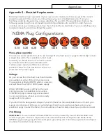
Page 45: ...ct a 3 phase kiln to 1 phase supply Voltage As you can see from the chart most Skutt models are available in either 208 or 240 volt versions The exception is Model KM714 which is universal and will fire with a 240V or 208V power supply While 120 240V supply is still by far the most common supply in residential communities 120 208V supply is increasingly encountered in commercial areas schools and ...

Page 46: ...6 50 KM1022 1 208 48 9984 6 6 50 KM1022 3 240 34 6 11520 8 15 50 KM1022 3 208 34 6 9984 8 15 50 KM1027 1 240 48 11520 6 6 50 KM1027 1 208 48 9984 6 6 50 KM1027 3 240 29 3 11520 8 15 50 KM1027 3 208 31 7 11000 8 15 50 KM1218 1 240 48 11520 6 6 50 KM1218 1 208 48 9984 6 6 50 KM1218 3 240 29 3 11520 8 15 50 KM1218 3 208 29 5 9984 8 15 50 KM1222 3 1 240 48 11520 6 6 50 KM1222 3 1 208 48 9984 6 6 50 KM...

Page 47: ...208 51 5 17300 4 Direct Wire KM1627PK LF 1 240 68 16300 3 Direct Wire KM1627PK LF 1 208 69 14300 3 Direct Wire KM1627PK LF 3 240 46 16300 6 Direct Wire KM1627PK LF 3 208 47 14300 6 Direct Wire KM1627PK 3 240 66 23600 3 Direct Wire KM1627PK 3 208 76 23600 3 Direct Wire For each additional 50 feet use heavier wire numerically two numbers lower for example instead of 10 use 8 If you anticipate instal...

Page 48: ... they are equipped with industrial gauge wiring and three types of elements for better firing balance Because of their high rating electrical codes require that they be direct wired by an electrician therefore no plug is included Mercury displacement relays are used for longer life and quieter operation The hinged control box is larger and compression connectors are used on the feeder wires for ea...

Page 49: ...the three terminal blocks Slide the thermocouple connectors off the terminal strip Lift the red control box up to remove it Unhook the draw pull catches and lift the sections using the handles provided To reassemble PK kilns Stack the sections in original sequence Place the switch box on its hinges Reattach the feeder wires in their original positions Make sure the connection is very tight to avoi...

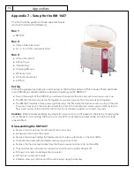
Page 50: ... are holes cast in the liner which hold the 2 inch 2 54 centimeter ceramic posts Carefully lay the fiber insert on top of the slab after the first section is placed in position and insert the posts Caution Before disassembling any Oval kiln be sure to turn off power to the kiln by throwing the circuit breaker or removing the fuse on its circuit Do not restore power to the kiln until it is fully re...

Page 51: ... sure the connection is tight to avoid electrical problems Reattach the thermocouple wires in correct order Reattach the screws which secure the control box to the kiln jacket KM 1627 Section Element Type Position Upper Top Bottom 1 Top Bottom 2 Intermediate 3 Intermediate 4 Master Center 5 Center 6 Center 7 Center 8 Lower Intermediate 9 Intermediate 10 Top Bottom 11 Top Bottom 12 Appendices ...

Page 52: ...ore hanging the controller on the wall loop the cord attached to the quick reference card over a screw so that it hangs below the controller when mounted Connecting to the kiln Single phase Switching capacity 48 Amps on 208 240V To operate the wall mounted controller simply engage the kiln plug in the receptacle located on the back of the controller Then plug the controller into the existing wall ...

Page 53: ...ark positioning the thumbscrew hole on top Mark the position of the small holes on the jacket Push hard or tap out with a nail and hammer the small screw holes Drill two 3 32 in 0 23 cm holes for the smaller sheet metal screws Drill through the metal only Install the flange with the sheet metal screws provided For the remaining installation steps consult the previous section on Thermocouple Instal...

Page 54: ...E A software error has occurred Press any key to display the elapsed firing time and the temperature when the error occurred Consult section on Error Codes for troubleshooting information F1 F2 F3 F4 F5 F6 F7 or F8 The controller is in RAMP HOLD mode The user needs to input an end temperature in ºF or ºC for each segment of the firing profile FAIL The thermocouple and controller are not properly c...

Page 55: ...lay to return to Idle Mode Flashes twice at the end of programming while the controller is processing the information you have input Flashing temperature and IdLE The kiln is in IdLE Mode The kiln is off and the display is showing the kiln s current temperature Alternating display of time and temperature The kiln is in a RAMP HOLD firing profile and is in the soak stage The display is indicating t...

Page 56: ... Automatic Kiln KM614 1 Phase 2W G MJH 6 29 06 Wiring Diagram Grnd green Relay Relay Current Sensor S C C S N Element Element Element X W 1 S 2 3 A C A B 1 2 1 2 3 4 4 3 L2 L1 W_7525 Automatic Kiln KM714 1 Phase 2W N G MJH 6 29 06 Wiring Diagram Grnd green Current Sensor Wiring Diagrams ...

Page 57: ... Phase KM1018 1 Zone Automatic Kiln Element Element Element Middle Ring Element MJH 3 23 06 Grnd green Relay Relay Sensor Current L2 Grnd green L1 CS CS Relay Relay 700 1 2 3 4 5 6 6 5 4 3 2 1 1 S 2 3 C A A W_7520 B Sensor X W Current Wiring Diagram 1 Phase 2 Wire G 1 Zone Automatic Kiln Top Ring Master Ring MJH 6 8 06 KM818 Wiring Diagrams ...

Page 58: ...ement Element Master Ring Element Top Ring CS CS Element Element KM822 KM1022 KM1222 1 Phase KM822 KM1022 KM1222 MJH 4 20 11 Automatic Kiln Models 1 Zone 3 Phase 3 Wire G Wiring Diagram Current W X Sensor B W_7569 A A C 3 2 S 1 700 Grnd green yel L1 L2 CS 6 6 5 4 5 4 3 2 3 2 1 1 Element Element Master Ring Element Top Ring CS CS Element Element L3 KM822 KM1022 KM1222 3 Phase Wiring Diagrams ...

Page 59: ... X W Wiring Diagram 3 Phase 3 Wire G 1 Zone Automatic Kiln MJH 6 30 06 KM1218 Sensor Current Relay Relay Relay CS CS Top Ring Element Bottom Ring Element Element Element 1 1 2 3 2 3 4 5 4 5 7 8 7 8 6 6 CS L2 L1 Grnd green yel 700 1 S 2 3 C A A W_7522 B X W Wiring Diagram 1 Phase 2 Wire G 1 Zone Automatic Kiln MJH 6 22 06 KM1218 Sensor Current Relay Relay Relay Wiring Diagrams ...

Page 60: ...e 1 Zone Automatic Kiln Top Ring Middle Ring Bottom Ring MJH 3 23 06 KM1027 KM1227 Grnd green Relay Relay Relay Sensor Current 700 CS CS CS 6 5 4 3 2 1 B W A C A 3 2 S 1 X W_7510 1 Phase 1 Zone KM1027 KM1227 Automatic Kiln Wiring Diagram L2 L1 MJH 4 13 06 Bottom Ring Top Ring Middle Ring 6 5 4 3 2 1 Relay Relay Relay Grnd green Sensor Current Wiring Diagrams ...

Page 61: ...minal Strip 1 Phase 2 Wire G Automatic Kiln Wiring Diagram Sensor Current Grnd green Bottom Ring Top Ring Middle Ring MJH 6 30 06 W_7528 700 S B W CS CS CS KM1227PK FUSED Fuse Fuse Fuse X Pilot Pilot Pilot MOV MOV MOV A C 4 3 2 1 L2 L3 L1 3 Phase 3 Wire G Automatic Kiln Wiring Diagram Transformer Relay Relay Relay Relay Relay Relay Sensor Current Grnd green Bottom Ring Top Ring Middle Ring Wiring ...

Page 62: ...nsor Current Relay Relay Relay Relay Relay Relay Grnd green Bottom Ring Top Ring Middle Ring MJH 4 14 06 W_7511 700 S B W CS CS CS KM1231PK FUSED Fuse Fuse Fuse X Pilot Pilot Pilot MOV MOV MOV A C 4 3 2 1 L2 L3 L1 Back Front Terminal Strip 3 Phase 3 Wire G Automatic Kiln Wiring Diagram Grnd green Relay Relay Relay Relay Relay Relay Bottom Ring Top Ring Middle Ring Sensor Current KM1231 PK 3 Phase ...

Page 63: ...utomatic Kiln Wiring Diagram Fuse Bottom Ring Top Ring Middle Ring Grnd green KM1627 PK 3 Phase KM1627 PK 1 Phase CS CS CS W B S 700 X MJH 7 6 06 W_7530 KM1627PK Fused Fuse Fuse Fuse Pilot Pilot Pilot MOV MOV MOV A C A 3 2 1 L2 L1 Fuse Back Front Terminal Strip 1 Phase 2 Wire Automatic Kiln Wiring Diagram Fuse Sensor Current Grnd green Relay Relay Relay Relay Relay Relay Bottom Ring Top Ring Middl...

Page 64: ...iln 1 Phase 2 Wire Wiring Diagram KM1627PKLF 1 Zone Grnd green Bottom Ring Top Ring Middle Ring L2 L1 L3 CS CS CS A C A 700 S X W B Current Sensor W_7533 MJH 7 6 06 1 3 2 MOV Pilot Front Terminal Strip Back Terminal Strips Automatic Kiln 3 Phase 3 Wire Wiring Diagram KM1627PKLF 1 Zone Bottom Ring Top Ring Middle Ring Fuse Fuse Fuse Fuse Relay Relay Relay Relay Relay Relay Grnd green Wiring Diagram...

Page 65: ... S 2 Wire G W_7527 MJH 6 30 06 KM 1 1 zone Wiring Diagram Transformer Contactor 3 Phase 40 Amp 3 Phase Plug 3 Phase Recept 250V MOV Socket Pilot Cord 190 250 Volts 700 BOARD PILOT T C A 6 5 4 3 2 1 S 3 Wire G W_7526 MJH 6 30 06 KM 1 1 zone Wiring Diagram Transformer KM 1 3 Phase KM 1 1 Phase Wiring Diagrams ...

Page 66: ...MENT RATE TEMP HOLD NOTES 1 2 3 4 5 6 7 8 PROGRAM 2 SEGMENT RATE TEMP HOLD NOTES 1 2 3 4 5 6 7 8 PROGRAM 3 SEGMENT RATE TEMP HOLD NOTES 1 2 3 4 5 6 7 8 PROGRAM 4 SEGMENT RATE TEMP HOLD NOTES 1 2 3 4 5 6 7 8 My Programs ...

Page 67: ...WARRANTY Some states do not allow limitations on how long an implied warranty lasts so the above limitation may not apply to you Dealers are not authorized to modify this Warranty or to make any additional commitments Skutt will not be responsible for promises not contained in this Warranty State Law Rights This Warranty gives you specific legal rights and you may also have other rights which vary...

Page 68: ...www skutt com 6441 SE Johnson Creek Blvd Portland OR 97206 503 774 6000 skutt skutt com ...

Reviews: