

•
Installation
•
Operation
In normal operation, the T-51A will connect the first
RINGING
telephone line to the Telecommunication Device. When the
Telecommunication Device goes
OFF HOOK
, the T-51A will place a
BUSY
across the other telephone lines. When the Telecommunication
Device hangs up, the T-51A will remove the
BUSY
from the other lines and
then it will wait for the next call. Whenever the Telecommunication Device
is activated for an
OUTGOING
call, the T-51A will automatically connect
the Telecommunication Device to the telephone line that modular cord #1 is
connected to.
If you are using the T-51A during working hours, you should either
have our Service Center install the
NON-INTERRUPT
Modification (call
for current pricing), or you can opt to disable the
BUSY OUT
feature. If you
do not choose either of these options, when the Telecommunication Device
grabs the line, anyone who happens to be on one of the other lines will notice
a dramatic drop in the audio level on their line.
To disable the T-51A during business hours, you can turn off the
Telecommunication Device, or you can simply unplug the T-51A from
power.
•
Multi-Line Connection
To cover more than three lines, you just plug the
LINE 1
cord from one
T-51A into the female jack of the next T-51A. You will notice that each
additional T-51A (other than the first unit) only gives you two more lines; so,
to cover up to eleven telephone lines, you would need five T-51A's.
•
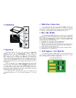
Busy Out Disable
You can disable the
BUSY OUT
feature of the T-51A by simply cutting
one trace on the circuit board inside the unit. If you decide to disable the
BUSY OUT
feature, you will also disable the
1A2
lamp indication (only
used on
1A2
and
COMKEY Key
Systems). To disable the
BUSY OUT
feature of the T-51A, do the following:
1)
Unplug the T-51A from power and all telephone lines.
2)
Open the T-51A (remove the 4 screws from the lid).
3)
Hold the circuit board (with the lid still attached) so that the placement of
the main parts on the circuit board is the same as the illustration below.
4)
Locate the circuit trace indicated below.
5)
Cut the circuit trace, between the circuit trace balls, as indicated below.
6)
Reassemble the T-51A and that's all.
•
Tech Support - 916-786-6186
If you have any problems getting the unit to work properly feel free to
give us a call. Technical Support is available between the hours of 7:30 AM
and 4:30 PM Pacific Time, Monday through Friday.
3 -LIN E S W IN G E R
T-5 1 A
M O D E L
E LE C T R O N IC S
Wall
Phone
Jack
Wall
Phone
Jack
Wall
Phone
Jack
Lin e 1
Lin e 2
Lin e 3
Cut this trace between the balls.
To disable the BUSY OUT,


