background image

Page 44 of 68

Page 45 of 68

SKIPPER

 Electronics AS

Edition: 

2021.11.04

SKIPPER

 Electronics AS

Edition: 

2021.11.04

ESN200 Operation and Installation Manual

ESN200 Operation and Installation Manual

Chapter: CONFIG software setup

Chapter: CONFIG software setup

Connecting the printer

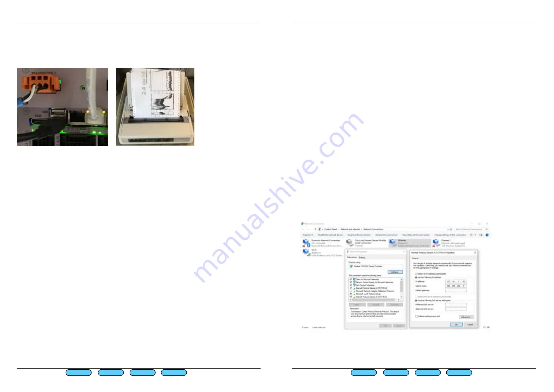
The printer needs to be connected to one of the two USB port in the JB70E2 unit, Some printers 

may not be electrically isolated from the power, in these cases a USB isolator is supplied , or can 

be purchased from skipper part EN-USB-ISO


Network printing

An alternative to the above USB printer is to print via Network printer. In this case a PC has to be 

connected to the network and SKIPPER service software can be used for printing.

PC connection Setup

Features available via JB70E2-SA second ethernet LAN connector to a PC with SKIPPER software:

-Printing to PC printer

-History download

-Software upgrade

The PC ethernet adaptor to be connected to the ESN200 needs to be preconfigured to a unique IP address  

on the same subnet mask as the ESN200. e.g. 172.16.1.xxx (The Display unit ESN200-SB default IP address 

is 172.16.1.109 and the electronic unit JB70E2-SA is 172.16.1.108.)

Setting up static IP address in Windows:

1: Click Start menu > Control panel > Network and sharing center or Network and internet > Network 

and sharing center.

2: Click change adaptor settings.

3: Right click on local area connection.

4: Click properties.

5: Select Internet protocol version 4 (TCP/IPv4)

6: Click properties.

7: Select Use the following IP address

The ESN Printing app is installed with the service software and a shortcut can be made to it in folder C:/

Skipper/servicesoftware/esnprinter.exe

First Page

Prev Page

Next Page

Last Page

First Page

Last Page

Prev Page

Next Page

Summary of Contents for ESN200

Page 1: ...Document no DM G005 SB Rev 2111 For software rev 1 1 3 Date 2021 11 04 SKIPPER Electronics AS www skipper no ESN200 Operation and Installation Manual Dual channel Multi frequency Echo sounder ...

Page 2: ...uicios IMPORTANT When doing service or repair please wait two minutes after power off before unplugging internal connectors Do not run the sounder for a long time with the transducer in air The transducer may be damaged Contents INTRODUCTION 4 Specification 6 MECHANICAL INSTALLATION 7 Installation Details 8 CONFIG SOFTWARE SETUP 11 ES Setup 12 Transducer setup 12 Main setup 15 Options 16 Options S...

Page 3: ... with expected depth limits 50 200kHz ETS50200T G 1 5 450m 200kHz ETN200T 1 5 300m 200kHz ETN200ST G 1 5 200m 50kHz ETN050T G 2 450m 38kHz ETN038T G 2 1000 Measuring Accuracy 2 20m Accuracy 0 5m Resolution 0 1m 20 200m Accuracy 5m Resolution 1m Output power Nominal 700W Max 1000W User functions Auto mode for all settings Manual control Gain Power TVG Frequency Transducer setup by part number Diagn...

Page 4: ...5 230VAC Power Consumption Display unit Nominal 6W Electronic unit 20W Display ESN200 SB 9 Resistive touch 400NITS Dimensions 242 x 158mm Weight 1 1kg 1 x LAN 2 x NMEA 0183 Outputs IEC61162 1 3 x NMEA 0183 Inputs IEC61162 1 Electronic unit JB70E2 SA Dimension 115x115x180mm Weight 1 5kg 2 x LAN IEC61162 450 5 x NMEA 0183 Outputs IEC61162 1 3 x NMEA 0183 Inputs IEC61162 1 1 x AUX in 2 x AUX out 1 x ...

Page 5: ...t If this is not possible a blister should be assembled This should have at least 0 3m of flat area in front of the transducer and be tear drop shaped Generally there should be nothing in front of the transducer that can cause turbulence and to the side nothing within 0 5m Positioning wiring of the units Length Transducer cable type 1 x shielded pair twisted pair recommended if available 25 40m Co...

Page 6: ... 03 10 06 02 05 09 R1 R2 12 08 01 04 11 0 V 24 V PULSE LEVEL OUTPUT ALARM 0 V 24 V N L G 24 V 0 V 0 V 24 V N G L 5 24V 5 24V SWITCH BAM VDR INS ECDIS RADAR OR BETTER RESET CAT 5e 6 1 2 3 11 7 5 4 12 10 8 4 6 3 7 1 5 9 8 2 7 8 4 5 6 3 1 2 2 1 2 1 3 2 NMEA 1 IN 12 10 08 06 04 02 11 09 07 05 03 DC AC AUX 0 V AUX IN 1 AUX OUT 2 AUX OUT 1 AUX 5 V R2 R1 1 01 AUX OUTPUT ADD RESISTOR TO GIVE MAX 100 mA 24...

Page 7: ...to the appropriate area of the vessel and select the transducer by part number This will change the parameters to match your transducer If you are not using a standard transducer then select other and the frequency max power and max expected range can be set for that Selectable transducer types Part number Type Approved for use ETN050 50 kHz of types ETN50 X G ETN50 X T Yes ETN200 200kHz of types ...

Page 8: ... the above transducers can be primary if a non approved transducer is used as the second transducer this must not be primary Settings available only in the case Part number is other Main setup Echosounder parameters are set by default but can be adjusted in the ES Setup Main Setup Auto functions will take control of range gain and frequency for ETS50200 Vessel image Change the design of the vessel...

Page 9: ...ved it must ping at least 2 20m range Minimum 36 ping per minute 20 200m range minimum 12 ping per minute This gives some leeway in when the system pings Multiplexed ping Config ES Setup Main Setup Multiplexed ON the system will take turns to ping on channel 1 and channel 2 This can be used if 2 transducers of the same frequency are installed and effect each other Synchronisation with external aco...

Page 10: ...are 2 channels 1 Output for NMEA 2 LAN input and output for IEC61162 450 messages This port can provide communication both by TCP IP V4 0 and using IEC61162 450 If being used it requires a network that does not exceed 60kbits second directed to the system The system will exert receive a maximum load of 40 datagrams second The network load should not exceed 20Mb s The LAN ports on this system suppo...

Page 11: ...uts Format Function __DDC X yy X C nn Dimming function X O N K D YY is the system will accept X and adjust to the user set level See dimming __XDR D x x M pos D x x M pos D x x M pos nn If the vessel has a draft sensor the fol lowing input can be used to automatically adjust the draft Draft sensor depth values x x draft value pos transducer position fwd aft prt str GPZDA Time and local time The sy...

Page 12: ...external beeper ShallDeepAlr both alarms DeepAlrBeep beeps for both alarms ShallDeep limit Out put change state when outside set limit Power failure changes when no power on JB70 Disabled Sync Out Changes when a second system can ping When enabled on one of the AUX outputs it will half the amount of pings to allow another system to ping For asynchronized pinging of two sys tems Ping Changes when t...

Page 13: ...ts are also available via NMEA using the EPV command see apppendix Please note Mute synch function only available as special option with option code from SKIPPER and may make the echosounder non Wheelmark approved Synch in Mute will create a warning if the number of pings are outside IMO requirement 36 pings per minute in 20m range or less and 12 in 20m range The opto isolated input and outputs ne...

Page 14: ...log heading ROT Depth from log alarm shallow alert deep draft mark gain TVG pic speed range show marks power frequency auto functions print A long 3 second press will show a menu of the available options RANGE is always available in the bottom left position with a single touch Button Description Show page Activate this transducer display Show marks Show changes in the system as vertical line with ...

Page 15: ...ay setup The Display setup menu gives access to the system parameters the dimming set up and the Net work parameters Screen setup Language Only English currently available Alarm sounder Internal alarm sounder is always on in ALF mode Button click Sound feedback on touching the screen NMEA loop test Testing of NMEA ports in JB70E2 SA with loop feedback on ports Sounder test This will beep at full v...

Page 16: ...ou wish to have a local setting for this use the button ignore The system will then use the predefined brightness level set in this con figuration The current dimming settings whether set by remote or locally are shown in the greyed out but tons Alert setup Alarm Shallow water Most critical alert Warning Example Power failure Less critical alert Caution Example Deep water Least critical alert Echo...

Page 17: ...ssages to be sent ALF or ALR with or without acknowledge of shallow water Escalation time 1m 2 3 4 5 m 2 min If escalation is selected on a warn ing this becomes an alarm after this time The system is compliant with 2018 version of IEC62923 The alerts setup page will allow the alerts to be setup by category an alert ID number being assigned to the alert according to the standard These alerts can b...

Page 18: ...2 7 3 6F SDALF 1 1 6 123805 05 B W U 3022 7 4 0 Power Reduction Display 24V 25 2V 42 SDALF 1 1 7 123755 55 B W U 3022 6 2 0 Power Failure Transceiver 24V 2F SDALF 1 1 8 123755 55 B W V 3022 7 5 0 Power Reduction Display 24V 25 2V 41 SDALF 1 1 9 123757 57 B W V 3022 7 6 0 Power Reduction System 3F SDALC 01 01 53 2 3022 6 2 3022 7 6 68 SDALC 01 01 54 2 3022 6 2 3022 7 6 6F SDALF 1 1 0 123817 17 B W ...

Page 19: ...erations are available the system cannot be remotely acknowledged Remote silencing is available CAT B ALF ACN ALC The system is connected to an approved INS All remote functions are available Responsibility transfer is available for all alarms and warnings allowing a remote system to take control and acknowledge the system Escalation type Escalation is used on all warnings System Error allows can ...

Page 20: ...n No beep No beep If responsibility is transferred the transferred alarm will remain passive in this system for the escalation time set in config alert setup screen Examples If connected to a central alarm management system and this fails the lack of an HBT NMEA message from the CAM will cause the system to take back control Diagnostics of alerts The following shows the NMEA output for an alarm te...

Page 21: ...lay If more than one display is in use this must be different Transmission Group The com plete system belongs to a group of systems This can be changed but all units must be in the same group Groups available are NAVD default RCOM PROP System Name The name to be reported on the LAN applications Network setup The system uses TCP IP for upgrade and as default is set to 172 16 1 108 109 Subnet mask i...

Page 22: ...be changed to activate printing from software version 1 0 6 Setup print button in Runtime Screen In runtime setup activate one of the information buttons to Printing This will show On or Off Setup printer type in Print Setup menu The printer is enabled and type selected in Config Print setup Select Printing ON select the correct printer and channel Printers EPSON350 OKI ML280 OKI ML 1190eco LAN us...

Page 23: ...A second ethernet LAN connector to a PC with SKIPPER software Printing to PC printer History download Software upgrade The PC ethernet adaptor to be connected to the ESN200 needs to be preconfigured to a unique IP address on the same subnet mask as the ESN200 e g 172 16 1 xxx The Display unit ESN200 SB default IP address is 172 16 1 109 and the electronic unit JB70E2 SA is 172 16 1 108 Setting up ...

Page 24: ...n can be setup to show the parameters that the user wishes to see or control but it also has an automatic function that takes over the control of range gain frequency and power of the system to minimize the required amount of user interaction The system has 1 mandatory alarm Shallow water and a second deep water alert In addition it gives alerts of system failures The system will have 1 or 2 trans...

Page 25: ...n take control of the auto parameters by setting Auto functions OFF The system will inform that it is taken out of Auto mode and the user then has full control The system can again be put into auto mode using on screen button if selected by pressing and holding a parameter or within the menus Selectable Information All the buttons on the side and bottom can be selected Except Range which is perman...

Page 26: ...es in the water and compensates Manual adjusting this will give stronger weaker signal near the surface and can be used to reduce strong fish or bubble layers Auto This function works together with gain to provide an acceptable pic ture and continuous bottom detection If not on screen this is available in menu ES Setup The value can be changed by pressing and holding Pic speed Picture speed select...

Page 27: ... including the relevant input s such as GPS Heading other depth measurements 24 Hours history is available by pressing CONFIG and then 24 Hours history By selecting table the depth of at least every minute and marks in between indicating changes or highlighted events such as alarms or auto changes are listed with time and position if available This can be viewed on the history page as a picture or...

Page 28: ...ice software Depending on what is input to the system or selected to be logged the system logs up to 4MB per 24 hours Each competed echogram is converted to a PDF file and can be extracted using the service soft ware on a separate PC via LAN Logging to file can log all depth history in different formats and all NMEA input and output history Log to Selection of the media to log to SD USB Internal H...

Page 29: ...n to tune the system once installed in the vessel Show Noise results Show the results of the noise test See below Noise self test will run a series of pings and measurement within the system to find the noise con ditions These can be inspected by pressing the show noise button The values shown should be below 20mV once installed unless otherwise stated High values can usually be reduced by improve...

Page 30: ... to the transducer ports of the JB70E2 SA unit and then running the ESN200 noise test for the appropriate frequency will allow the user or service technician to check the signal output and noise characteristics of the system Using the transducer tester the connected transducers can be analysed to see if their resonance impedance is as expected Lost bottom or input information If the system cannot ...

Page 31: ...designed for flushmount installation 242 158 125 140 17 34 5 4 3 6 5 125 224 224 3 32 3 37 148 2 140 4 1 155 155 32 3 37 CUT OUT C 2 3 1 4 B A D E F Approved by date ST 2017 11 16 Designed by date Outline drawing PC 2017 11 16 Name CN All sharp edges to be broke or deburred Material N A Appendix 1 Installation drawings Optional wallmount desktop bracket Part number MG 0002 Mounting bracket for 9in...

Page 32: ...awings ENS518 SA Transducer selector The ESN200 has two transducer terminals selectable from software A transducer selector switch can be installed if more than two transducers are required The transducer selector switch will only be able to select between two transducers of same type and frequency There are no selector feedback to ESN200 for indication of for aft transducer is selected First Page...

Page 33: ...mote control The ESN200 has a number of NMEA message inputs that can be used to remote control the unit THese use the EPV format and currently the following are available To the JB unit XXEPV C SD 0108 0002 0 nn Standby off XXEPV C SD 0108 0002 1 nn Standby on XXEPV C SD 0108 2001 0 nn Mute OFF XXEPV C SD 0108 2001 1 nn Mute ON XXEPV C SD 0108 2001 2 nn Sync in ping now when mute is on or Aux inpu...

Page 34: ...eed The amount of time presented on the screen DBT Depth below transducer DBS Depth below surface DBK Depth below keel Draft Depth from water surface to the lowest point of the vessel Offset Distance from Transducer to the lowest point of the vessel DPTH Depth M Meters ft Feet fm Fathoms m s Speed in meters second kHz kilohertz Frequency hr hour min minute A Automatic mode system self adjusts rang...

Page 35: ...SKIPPER Electronics AS Telephone 47 23 30 22 70 Enebakkveien 150 www skipper no P O Box 151 Manglerud E mail support skipper no 0612 Oslo Norway Co reg no NO 965378847 MVA ...

Reviews: