


www.skf.com/lubrication
1
English
Installation
Notice
Operate the pressure switch within the specified
technical data only. The pressure switch must
not be exposed to high temperatures or rapid
pressure increases.
Do not touch the membrane of the flush-
mounted sensor: it can tear or become defor-
med.
–
Always depressurize and disconnect pressure switches
from the power supply before mounting.
–
Observe the following when mounting outdoors or in a
damp environment:
Select a mounting location that allows splash and
condensation water to drain away. Fluids must not be
allowed to accumulate on sealing surfaces.
Connect the device to the power supply immediately
after mounting to prevent moisture from entering the
connector. Otherwise fit a suitable protective cap to
prevent the ingress of moisture. The protection class
specified on the data sheet only applies if the device is
connected.
If there is a danger of damage from lightning strikes or
overvoltage, mount an overvoltage protection between
the power supply unit or switch cabinet and the
device.
–
In hydraulic systems, position the device in such way
that the pressure connection faces upwards (venting).
–
Mount the device in a location protected from direct
sunlight. Sunlight may affect the functionality of the
device or damage it.
–
When installing devices with relative reference in the
housing (small bore next to the electrical connection),
make sure that the relative reference required for the
measurement is protected against dirt and moisture. If
the device is exposed to fluids, the relative reference
blocks the air pressure compensator. Accurate meas-
urements are not possible when this happens. And
there may also occur material damage to the device.
–
No mechanical tension should be placed on the pres-
sure connection during installation as this may displace
the characteristic curve. This applies in particular to
extremely small pressure ranges and devices with a
plastic pressure connection.
Intended use
The pressure switches were designed to monitor the
pressure of lubricants compatible with stainless steel,
ceramics and fluoroelastomers (FKM). Depending on the
type of device and the mechanical connection the pressure
switches are suitable for the most different fields of appli-
cation.
The pressure switch is installed in a machine or integrated
into a system. Proper functioning in accordance with the
specifications in the technical data is ensured only when
original SKF accessories are used. Using other compo-
nents will void the warranty.
Modifications to the pressure switch or non-approved use
are not admissible and will result in a loss of warranty and
void any liability claims against the manufacturer.
Safety instructions
Carefully read the operating instructions prior to
integrating/commissioning the pressure swit-
ches.
These pressure switches must not be used in
applications in which the safety of persons is
dependent on the function of the device (not a
safety component according to EC Machinery
Directive).
Installation and start-up
are to be performed only by
trained specialists.
The
operator
is responsible for ensuring that local safety
regulations are observed.
In particular, the operator must take measures to ensure
that a defect in the object detection systems will not result
in hazards to persons or equipment.
In case of defects or a failure that cannot be remedied,
take the pressure switch out of service and secure it
against unauthorized use.
Downloading the operating instructions
These operating instructions are also available on the
Internet at www.skf.com/lubrication
Validity
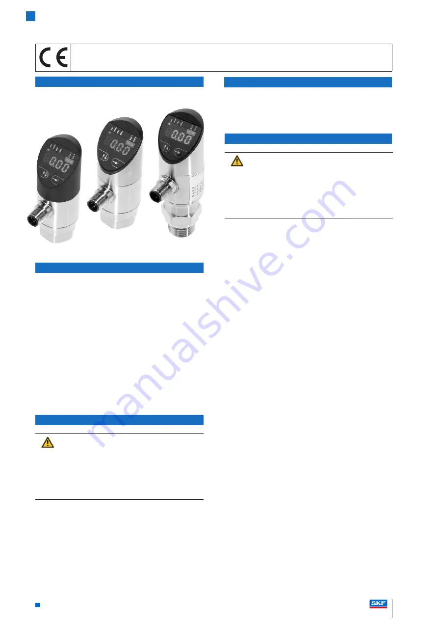
These instructions apply to the following pressure switches:
–
234-11145-3; 234-11145-4; 234-11145-5
–
234-11145-9
Standard
High-End
High-End
Flush-Mounted
EU directives: 2014/30/EU (EMC); 2011/65/EU (RoHS II)
Standards: EN 61000-6-4:2011 (emission), EN 61000-6-2:2006 (interference resistance); EN 50581:2013
Emission tests: Radio noise emission EN 55011:2016 Group 1, classes A and B
Standard, High-End and High-End Flush-Mounted Pressure Switches


