background image

SITEC S.r.l. Industrial electronics 


www.sitecsrl.it


User Manual TRG 72x72 

R2.A 

Pag. 11 

4.0  CONFIGURATION MENU 

4.1  M

ENU CONFIGURATION KEYS


To change the values, you have to act on the   key to increase the value or on the    key to decrease it. 
 
These keys function with one digit each time but, if pressed for more than half a second, the value increases 
or decreases rapidly and, after three seconds pressed, the speed increases even more, in order to allow the 
rapid achievement of the desired value. 


4.2  H

OW TO ENTER

-

EXIT

-

SURF THE CONFIGURATION MENU


To access the thermoregulator configuration menu, simply press once any one of the ( ,  , OK) 

keys beneath the thermoregulator. 


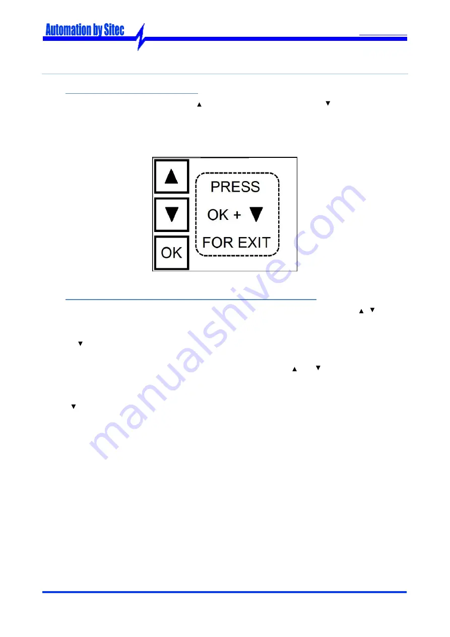
To exit the configuration menu, you have to go back all the menu "hierarchy" while pressing the 

OK 

 (

EXIT

) keys, or you can wait 10 seconds without pressing any button, then the thermoregulator 

will automatically close the configuration menu without saving the ongoing changes. 


To surf/increase/decrease the menu values you have to press the 

 and   keys. 


To confirm a selection, you have to press the 

OK 

key. 


To cancel a change or go back to the upper level menu, you have to press simultaneously the 

OK + 

EXIT

 keys


(

in this sequence

). 

Summary of Contents for TRG 72x72

Page 1: ...SITEC S r l Industrial electronics www sitecsrl it User Manual TRG 72x72 R2 A Pag 1 USER MANUAL 72X72 TRG 72 x 72 Thermoregulator for ovens ...

Page 2: ......

Page 3: ...ICAL 9 ELECTRICAL 9 OUTPUTS K1 K2 9 ENVIRONMENTAL 9 3 2 FACTORY SETTINGS 10 4 0 CONFIGURATION MENU 11 4 1 MENU CONFIGURATION KEYS 11 4 2 HOW TO ENTER EXIT SURF THE CONFIGURATION MENU 11 4 3 MENU HIERARCHICAL SCHEME 12 5 0 SETTING PARAMETERS 13 5 1 SET THE SETPOINT TEMPERATURE 13 5 2 CHANGE THE TEMPERATURE PROBE 13 5 2 1 Operational range of the temperature probes 13 5 3 CHANGE THE TYPE OF SETTING ...

Page 4: ......

Page 5: ...rature to enable the second heater Minimum time to restart the heater heaters Instead with the PID setting single action you can set the following parameters Proportional band Integral time Derivative time Period of the output PWM signal In addition three different kinds of temperature probes are supported and they can be selected through the thermoregulator menu Thermocouple K Thermocouple J PT10...

Page 6: ...NS 72 72 81 15 4 24 67 4 DIS N 052 rev 0 TC PT100 K1 K2 1 2 3 4 5 6 7 8 9 10 11 12 66 8 4 14 6 11 6 14 6 31 6 Please note dimensions are expressed in millimeters 11 LEDs for the setpoint position N 3 7 segment displays Scale of the setpoint temperature Rotating ring nut to set temperature With the IP54 protection class 2 Status LEDs for the relay outputs Setpoint LED ...

Page 7: ...has adequate ventilation and avoid installation in containers that house devices that may cause the instrument to operate outside the stated temperature limits Install the instrument as far away as possible from sources of electromagnetic disturbances such as motors remote control switches relays solenoid valves etc 2 2 TERMINAL BOXES AND CONNECTION ELECTRICAL SCHEME 1 Clips to connect the thermor...

Page 8: ...bles are screened it is advisable to connect them to the ground on one side only Finally it is recommended to check that the set parameters are the right ones and that the application works correctly before connecting the outputs to the actuators in order to avoid plant anomalies which may cause damage to people things or animals Sitec S r l and its legal representatives accept no responsibility f...

Page 9: ...0 g Provided with connectors and hooks Terminal box connections Screw terminal Max 1 5 mm 2 cable Assembly Assembly within a device ELECTRICAL Supply voltage 24 VAC DC 10 50 60 Hz Max power demand 250 mA OUTPUTS K1 K2 Max electrical load 6 4 A AC1 AC3 Max voltage 230 V Vac Electrical operations 5x10 5 Mechanical operations 10 7 ENVIRONMENTAL Temperature of operation From 0 to 60 C Temperature of t...

Page 10: ...robe tEr Thermocouple K rEG Type of setting OnF On Off setting Hy5 1nF Lower Hysteresis 0 C Hy5 5UP Upper Hysteresis 0 C T5H Temperature to start the second heater 0 C Ctr Control temperature 0 C Pb Proportional band 50 C 1nt Integral Time 200 s dEr Derivative Time 50 s Cyt Period of the PWM signal 20 s LP5 Min time to reactivate the outputs 0 s ...

Page 11: ...ue 4 2 HOW TO ENTER EXIT SURF THE CONFIGURATION MENU To access the thermoregulator configuration menu simply press once any one of the OK keys beneath the thermoregulator To exit the configuration menu you have to go back all the menu hierarchy while pressing the OK EXIT keys or you can wait 10 seconds without pressing any button then the thermoregulator will automatically close the configuration ...

Page 12: ... to 20 C T5H Temperature to start the second heater Visible only with On Off setting o From 0 C to full scale temperature Ctr Control zone Visible only with On Off setting o From 0 C to full scale temperature Pb Proportional Band Visible only with PID setting o From 1 to 999 C 1nt Integral Time Visible only with PID setting o From 0 to 999 seconds dEr Derivative Time Visible only with PID setting ...

Page 13: ...tor K J if you want to use the thermoregulator J or Pt1 if you want to use the PT100 then confirm your choice by the OK key Once the change is done exit the menu and connect the temperature probe you have just selected to the clips of the thermoregulator see paragraph 2 2 than check that the thermoregulator doesn t signal any er ror see paragraph 6 1 Please note for the thermocouple K or J be sure...

Page 14: ...tervention of the final setting element that in case of a relay could rapidly wear out 5 3 2 PID Setting The temperature setting via PID allows to obtain an accuracy significantly higher than the simple On Off control the calculation of the PID is done by adding the contributions of the proportional see paragraph 5 7 integral see paragraph 5 8 and derivative effect see paragraph 5 9 In this case b...

Page 15: ...imprecision and weak fluctuations around one single threshold value The regulator behaves in the following way Deactivate K1 and or K2 see paragraph 2 2 when the temperature of the oven is higher than the setpoint higher hysteresis Activate K1 and or K2 when the temperature of the oven is lower than the setpoint lower hys teresis If the oven temperature is higher than the setpoint lower hysteresis...

Page 16: ...perature to enable the second heater both the outputs K1 and K2 to set the temperature are always used Therefore starting both the outputs when the oven temperature is lower than the setpoint lower hysteresis temperature and deactivating both the outputs when the oven temperature is higher than the setpoint higher hysteresis temperature When the setpoint temperature is lower or equal to the temper...

Page 17: ...her than the setpoint control area temperature and lower than the setpoint lower hysteresis temperature then only the output K1 is enabled If the oven temperature is lower than the setpoint control area temperature and than the set point lower hysteresis temperature then are enabled both the K1 and K2 outputs In order to deactivate the control area you just have to set it to zero while in order to...

Page 18: ...rature is higher than the setpoint temperature If you reduce the proportional band the accuracy of the controller improves since a smaller error is enough to cause a certain change in the output power There is however a limit to the reduction of the proportional band at a certain point the system starts to self oscillate and the band must be increased In the diagram you can see how the power duty ...

Page 19: ... integral control the output power increases as long as the temperature is equal to the setpoint At this point the out put of the integrator stops increasing and keeps a steady power The integral control is characterized by the Integration time described as the time necessary in order for the integral output to vary from zero to its maximum in the presence of a fixed error equal to the proportiona...

Page 20: ...nal and integral is independent from the setpoint namely the derivative gives a contribution only according to the changing speed of the feedback without considering the setpoint position therefore a step change of the setpoint will not involve any change on the derivative To disable the derivative time you have to set it to 0 Please note the derivative time can be set up only after having enabled...

Page 21: ...od can be set up only after having enabled the temperature setting via PID see paragraph 5 3 Hereafter the diagram shows a typical behaviour of the PID with PWM output 5 11 MINIMUM TIME TO REACTIVATE THE OUTPUTS To set up the minimum time to reactivate the outputs you have to enter the configuration menu see para graph 4 2 enter the LP5 level see paragraph 4 3 and then select the desired value and...

Page 22: ...rmoregulator operational range then restart the thermoregulator E 4 The external temperature temperature probe of the oven is in under range lower than 0 C Check that the oven temperature is higher than 0 C otherwise the problem is as cribed to a malfunctioning of the temperature probe connected with the thermoregulator E 8 The external temperature temperature probe of the oven is in over range Ch...

Page 23: ......

Page 24: ...evise this document if necessary without notice in order to adapt it to future developments and or new business needs Without express authorization the disclosure of this document even if partial is prohibited Moreover Sitec S r l accepts no responsibility arising from the use of this document SITEC S r l Industrial Electronics Via Antonio Tomba 15 36078 Valdagno VI ITALY Tel 39 0445 431576 Fax 39...

Reviews: