båÖäáëÜ
59 38 399 D3352
D3352.076.01.13.02
07.2008
6 – 9
Tab 6
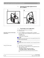
6.1 Replacing the height adjustment motor (M1_4)/spindle
6.1
6.1.2
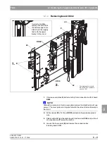
Removing board DX32
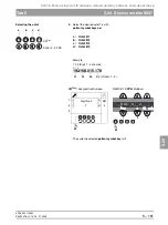
1.
Unscrew cover plates
E
(bottom and top) from connection box
F
of board
DX32
.
NOTE
i
Cable
L3
can remain on the top cover plate (remove the shield terminal if nec-
essary). The cover plate can simply be folded to the side and stored laterally in
the stand.
z
Pull connector
X2
off of board
DX32
and detach the protective ground
wire.
2.
Detach cable
L2
from the cable tie and from terminal
X100
and pull it out
of connection box
F
toward the bottom.
3.
Loosen the four screws
(G)
and remove the connection box
including board DX32.
F
E
L3
L2
X100
L3
1.
2.
3.
G
G
G
G
DX32*
*
The drawing shows board
DX32 with a unit hardware
version
≤
AG.
In order to facilitate
removal of board DX32,
the bottom edge of the
slide should be roughly
flush with the upper
bracket in the stand.
Summary of Contents for ORTHOPHOS XG 3 DS
Page 4: ......
Page 9: ...ORTHOPHOS XG 1General information...
Page 12: ...59 38 399 D3352 1 4 D3352 076 01 13 02 07 2008 Tab1...
Page 59: ...ORTHOPHOS XG 2 Messages...
Page 124: ...59 38 399 D3352 2 66 D3352 076 01 13 02 07 2008 2 6 List of available service routines Tab 2...
Page 125: ...ORTHOPHOS XG 3 Troubleshooting...
Page 153: ...ORTHOPHOS XG 4 Adjustment...
Page 269: ...ORTHOPHOS XG 5 Service routines...
Page 433: ...ORTHOPHOS XG 6 Repair...
Page 436: ...59 38 399 D3352 6 4 D3352 076 01 13 02 07 2008 Tab6...
Page 530: ...59 38 399 D3352 6 98 D3352 076 01 13 02 07 2008 6 21 Replacing cables Tabs 6...
Page 531: ...ORTHOPHOS XG 7 Maintenance...
Page 577: ...b 59 38 399 D3352 D3352 076 01 13 02 07 2008...


