background image

63 76 482 D 3572

D 3572

.

031.01.04

.

02 12.2015

67

Sirona Dental Systems GmbH 

9 Appendix

Installation Instructions Facescan

9.2 Conversion instructions for non-"Facescan ready" units

båÖäáëÜ

9.2.13

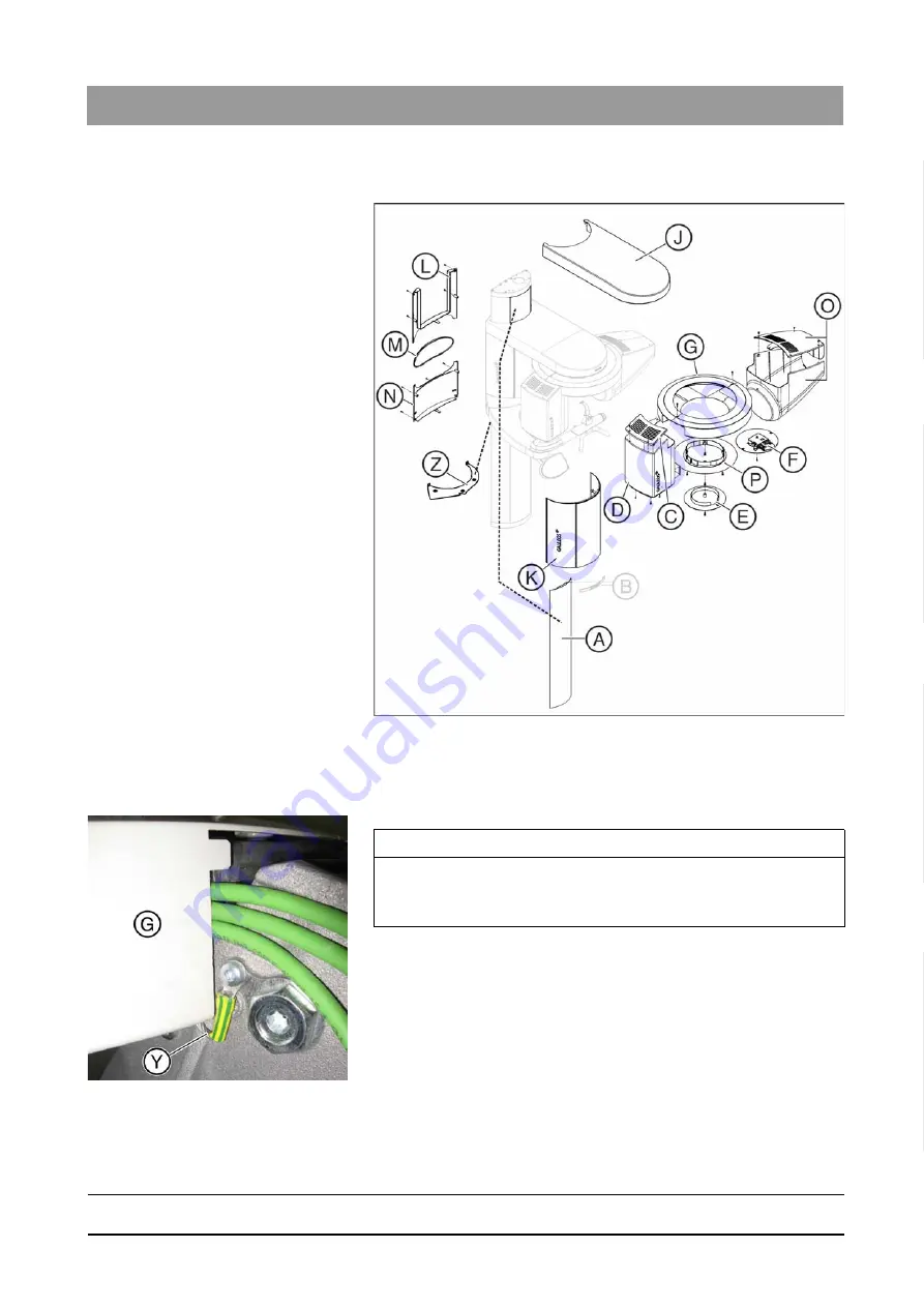
Attaching cover parts

➢ Attach the following cover parts (pay attention to the order!):
1. Protective cover (Z)
2. Ring cover bottom (P)
3. Ring cover top (G)

4. Ring center cover (E) (for devices without head attachment)

or

Head attachment exposure unit (F) (for devices with head 

attachment)

5. Tube assembly cover rear (D)
6. Tube assembly cover front (C)
7. Arm cover (J)
8. Rear cover sliding plate, bottom (N)
9. Rear cover sliding plate, center (M)
10. Rear cover sliding plate, top (L)

IMPORTANT

Possible assembly errors
The grounding strap (Y) must be fed along the underside of the cover 

(G).

Summary of Contents for Facescan

Page 1: ...k W f f NOKOMNR c b b Cover page...

Page 2: ......

Page 3: ...er documentation required 9 3 Safety instructions 10 3 1 Modifications to the unit 10 3 2 Fixed connection 10 3 3 Electromagnetic compatibility 10 3 4 Electrostatic discharge 10 3 5 Switching the unit...

Page 4: ...34 7 2 Connection to the network 34 7 2 1 Configuration 34 7 2 1 1 Explanation 34 7 2 1 2 Configuration options 34 7 2 1 3 Type 1 Configuration using the Facescan USB stick 35 7 2 1 4 Type 2 Configura...

Page 5: ...s in the stand 59 9 2 6 Attaching board DX32 61 9 2 7 Connecting switch S1 61 9 2 8 Removing the laser module 63 9 2 9 Removing the cable conduit with cable L13 on the ring 63 9 2 10 Lay cable conduit...

Page 6: ...tient The Instructions for Use and the Inspection and Maintenance Instructions of the GALILEOS and the Facescan must be followed 1 2 System requirements SIDEXIS and GALILEOS version GALILEOS firmware...

Page 7: ...afety information provided in the present operating instructions Such information is highlighted as follows Tip Information on making work easier DANGER An imminent danger that could result in serious...

Page 8: ...Facescan The network cable of the network connector being used must allow two IP addresses GALILEOS Facescan Also at the same time the IP addresses of the following network components must be accessi...

Page 9: ...Operator s Manual Order No 6376334 Installation Instructions GALILEOS Installations Instructions Order no 6125574 Worldwide 6125608 U S GALILEOS ORTHOPHOS XG 3D Software Installation Order no 61 42 3...

Page 10: ...bserve the specifications stated in the installation requirements Portable and mobile RF communications equipment may interfere with medical electrical equipment Therefore the use of mobile wireless p...

Page 11: ...tion Service engineer The valid radiation protection regulations and measures must be observed The statutory radiation protection equipment must be used During an exposure the service engineer should...

Page 12: ...ESCAN unit CAUTION Risk of injury The installation must be carried out in accordance with the requirements stated in our Installation Instructions Installation may be carried out only by personnel spe...

Page 13: ...D 3572 031 01 04 02 12 2015 13 Sirona Dental Systems GmbH 4 Configuration Installation Instructions Facescan 4 1 System overview b 4 Configuration 4 1 System overview Complete unit overview A GALILEOS...

Page 14: ...04 02 12 2015 4 Configuration Sirona Dental Systems GmbH 4 1 System overview Installation Instructions Facescan Overview of Facescan C Status display see section Status displays 15 D Illuminated stri...

Page 15: ...tched off FaceScan components have shut themselves down A firmware update using the FaceScan USB stick has been completed Off On Standby Flashing Off Exposure readiness Device ready for data transfer...

Page 16: ...LEOS units earlier than serial number 9000 Not FaceScan Ready units Geometry phantom Cable L78 Cable L77 Damage following delivery Indicators Indicators FaceScan Shock indicators have been put on the...

Page 17: ...structions Facescan b Enter the state of the indicators in the startup report in the case of warranty claims Disposal of packaging materials Disposal of packaging materials Return the packaging materi...

Page 18: ...Installation Sirona Dental Systems GmbH 6 1 Preparation Installation Instructions Facescan 6 Installation 6 1 Preparation The first work steps The first work steps 1 Move the arm B up to 1260 over th...

Page 19: ...ving cover parts Remove the following cover parts pay attention to the order 1 Spacer B 2 Lower cover profile A 6 3 Conversion of non Facescan ready devices Scope GALILEOS Comfort unit up to series nu...

Page 20: ...through the cable tie A on the Ethernet cable L77 L72 Securing 1 Insert two plastic clamping terminals into the shaft S 2 Tip Prevent the plastic clamping terminals from slipping using adhesive tape 3...

Page 21: ...on without board DX41 1 Push the cable cover I upwards 2 Plug Ethernet cable L77 L72 into the POE socket of the PoE module 3 To fasten slide the cable cover I downwards again as far as possible IMPORT...

Page 22: ...o the BU2 socket of the PoE module 6 Plug cable L71 into the BU1 socket of the PoE module 7 Plug cable L71 into the SC SC socket 8 Route cable L76 as shown in the image T Cable connections to the PoE...

Page 23: ...tions to terminal K1 1 Connect cable L76 BN brown to terminal K1 1 orange 2 Connect cable L76 WH white to terminal K1 2 orange 3 Fasten cable L76 as low as possible downwards with the cable clamp G 6...

Page 24: ...Instructions Facescan 3 Put the new X ray detector cover V on 4 Route cable L78 L74 and gray cable L78 CI FSB1 through the slot N of the X ray detector cover V 5 Screw down the new X ray detector cove...

Page 25: ...ttention to the order 1 2x cover profile A 2 Spacer B 3 Front cover sliding plate K 6 7 Attaching the scan unit 6 7 1 Screwing in the scan unit Preparation Preparation for screwing in the scan unit 1...

Page 26: ...only loosely 3 Mount the installation aid C from below on both sides onto the first cooling vent H of the face scan unit 4 Insert the fastening element F into the installation aid C NOTICE Important d...

Page 27: ...on both sides from the parked position L delivered condition to the function position M 9 Screw the scan unit down from below with the safety screws E In so doing the screws should pierce through the...

Page 28: ...lly 6 7 2 1 Step 1 Connect IMPORTANT The mounting aid C remains with the customer IMPORTANT Removing the transport lock The transport lock B and the wing screws A are required if any item has to be re...

Page 29: ...d is open 3 Read the MAC address on the FACESCAN modular board at position X and note this down 4 Plug cable L78 CI FSB1 in slot X1 on the FACESCAN modular board 5 Fasten cable L78 CI FSB1 to the side...

Page 30: ...steps Explanation Depending on the intended network configuration different work steps are required Selection The network should later be configured using a USB stick The network should later be conf...

Page 31: ...disinfecting agents with REF number For a continuously updated list of approved agents please visit www sirona com To access the online portal for technical documentation follow the SERVICE Technical...

Page 32: ...with an assembled protective cover T The subsequent network should be configured using network cables 3 Read the serial number on the identification plate S and record this on the device certificate...

Page 33: ...the scan unit b Version 1 Network configuration via USB stick 1 Screw the right end cap J with two screws K down on the scan unit 2 Do not screw the cover cap A down tightly Version 2 Network configu...

Page 34: ...ly be made through the network In so doing the Facescan s integrated web dialog is called up 7 2 1 2 Configuration options Factory setting IP address changeable Default setting 192 168 16 240 Subnet m...

Page 35: ...for operation 7 Insert the FaceScan USB stick into the USB port of the FACESCAN board The FaceScan will be configured Both LEDs of the status display light up 8 Wait until the light on both the LEDs...

Page 36: ...cescan_settings log 3 Check the entries in the log file If the configuration has been successful the log file should state Network configuration successful 4 Remove the USB stick from the PC Closing t...

Page 37: ...168 16 xx network otherwise no network connection can be achieved Using a network cable connect the PC directly to the GALILEOS media converter with installed Facescan Opening the web dialog general...

Page 38: ...iguration Confirm the configuration with the Configure Network button The Facescan restarts with the modified settings 7 2 2 Connecting with a network The configuration was conducted successfully see...

Page 39: ...7 In the MAC address text field enter the MAC address of the FaceScan 8 In the GALILEOS selection field select the GALILEOS unit on which the FaceScan is installed 9 Confirm your settings by pressing...

Page 40: ...e Facescan Calibration failed Please error message is displayed the calibration has failed The calibration process must be repeated 8 In the event of a successful calibration i e with no error message...

Page 41: ...will be tinged A white balance must be carried out in the following circumstances The first installation Making changes to environmental lighting You have updated the device software firmware Opening...

Page 42: ...nutes up to 20 minutes in the event of errors In the event of errors If the white balance does not work then the white balance procedure must be repeated The FaceScan restarts The white balance is com...

Page 43: ...e visible Artifacts Artifact A single small spike Reason Too light or lighting too direct Tolerance Height A maximum of 1 5 times a grid space Diameter A maximum of 3 times a grid space Number A maxim...

Page 44: ...ure duplication Tolerance Size of the area A maximum of three grid spaces Number A maximum of four areas with structure duplication Artifact C the vertical edges of the 3D calibration phantom are not...

Page 45: ...tructions Facescan 7 6 Test exposure b 7 6 3 Example 3 The exposure is not okay Artifact E very wavy surface Reason Too light or lighting too direct Artifact F strong duplication effect of the structu...

Page 46: ...and software version in the attached document Installation Report and Warranty Passport 2 Complete the remaining points together with the customer 3 Hand over the copy marked For the customer to the c...

Page 47: ...Final work Installation Instructions Facescan 8 1 Filling in the installation report and warranty passport b 4 Fax the For the dealer copy back to Sirona immediately after the installation IMPORTANT T...

Page 48: ...uses the compatibility list as evidence of the installed SIDEXIS system s EC conformity The list is structured in such a way that only the white fields need to be completed The original list remains...

Page 49: ...Unit handover Unit handover Give the customer all of the patient positioning aids test phantoms and special tools included in delivery including packaging These are important components of the unit an...

Page 50: ...tube assembly and rear tube assembly covers Measuring setup Ground wire test Measuring setup for protective ground wire test Check whether the ground wire resistance complies with the specifications A...

Page 51: ...nt table check whether the protective ground wires are fastened according to the specifications Check whether plain washer tooth lock washer and cable lug are installed on the protective ground wire i...

Page 52: ...GmbH 9 1 Checking the protective ground wires Installation Instructions Facescan Measuring point G Measuring point G Measuring point H Measuring point H G Stand arm measuring point G on measuring poi...

Page 53: ...ver parts pay attention to the order 1 Top cover profile A 2 Front cover sliding plate K 3 Rear cover sliding plate top L 4 Rear cover sliding plate center M 5 Rear cover sliding plate bottom N 6 Arm...

Page 54: ...9 2 2 Removing board DX32 1 Unscrew the bracket C The bracket C is located in front of board DX32 2 Move the stand to a height of 1260 control panel display 3 DANGER Potentially lethal shock hazard D...

Page 55: ...op covering plate E 9 Remove connector X2 from board DX32 and remove the protective conductor 10 Remove cable L2 from terminal X100 and pull it downwards from out of the connection box F 11 Remove con...

Page 56: ...le L1 from switch S1 2 Disconnect cable L1 from the ground point F 3 Loosen the two screws A 4 If not present Mark the position of the screw B on the stand 5 Make a note of the position of the screw B...

Page 57: ...n Instructions Facescan 9 2 Conversion instructions for non Facescan ready units b 7 Remove the power cable from terminal K1 8 Unscrew the mains filter plate 9 Remove the cable covers I and J of the r...

Page 58: ...s base 2 Insert new energy chain 1 in the stand 3 Screw down the mains filter plate 4 Screw the new energy chain down in the position marking of the old energy chain IMPORTANT Assembly instructions Pa...

Page 59: ...te through the ferrite core twice C two hoses 7 Screw the external PE cable B down on the ground bolts D 9 2 5 Routing new cables in the stand 1 Lay the cable harness L77 as shown through the opening...

Page 60: ...tions Facescan 3 Lay Ethernet cable L77 L72 on top 4 Route Ethernet cable L77 L72 through the arm opening to DX1 5 Route Ethernet cable L77 L72 and the ground strap in the right hand cable duct 6 Prot...

Page 61: ...h S1 Disconnecting cable L2 from switch S1 1 Remove cable L2 BU from switch S1 4 2 Remove cable L2 BN from switch S1 1 Connecting cable L2 to switch S1 1 Insert cable L2 BU into the flat power strip o...

Page 62: ...er supply cable L77 L70 BN brown to switch S1 above right 3 Connect power supply cable L77 L70 GN green with flat power strip to switch S1 below left 4 Connect power supply cable L77 L70 BK black with...

Page 63: ...module 2 Allow the plate A to hang carefully 9 2 9 Removing the cable conduit with cable L13 on the ring 1 CAUTION Risk of injury The covering plate can have sharp edges Remove the covering plate A c...

Page 64: ...Ethernet cable L77 L72 in the ST coupling S of cable L78 L74 5 Fasten the ST coupling S to the arm with the aid of two adhesive sockets and two cable ties see image IMPORTANT Possible assembly errors...

Page 65: ...o the ring 2 Route cables L78 L73 and L78 L74 as shown on the duct to the ring 3 Screw the grounding strap E to the ring tightly 4 Screw down the plate P with the laser module 5 Route cable L78 L73 to...

Page 66: ...3 to the X ray detector 1 Insert cable L78 L73 into socket X201 on board DX89 2 Route gray cable L78 CI FSB1 from the plug housing of cable L78 L73 forward toward the ring 3 Fasten cable L78 L73 to th...

Page 67: ...Protective cover Z 2 Ring cover bottom P 3 Ring cover top G 4 Ring center cover E for devices without head attachment or Head attachment exposure unit F for devices with head attachment 5 Tube assemb...

Page 68: ...the receptacle element To do this move the rotary knobs on the head fixation device to a vertical position Then align the receptacle element so that the laser light is shown in the middle of the vert...

Page 69: ......

Page 70: ...t K p a p d e OMNR p W m d a PRTOKMPNKMNKMQKMO NOKOMNR KJk KW NON MTO p a p d e rp W c PN aJSQSOR _ d p a I f K QUPR p a I k OUOTP rp l k SP TS QUO a PRTO K K...

Reviews: