63 76 482 D 3572
D 3572
.
031.01.04
.
02 12.2015
59
Sirona Dental Systems GmbH
9 Appendix
Installation Instructions Facescan
9.2 Conversion instructions for non-"Facescan ready" units
båÖäáëÜ
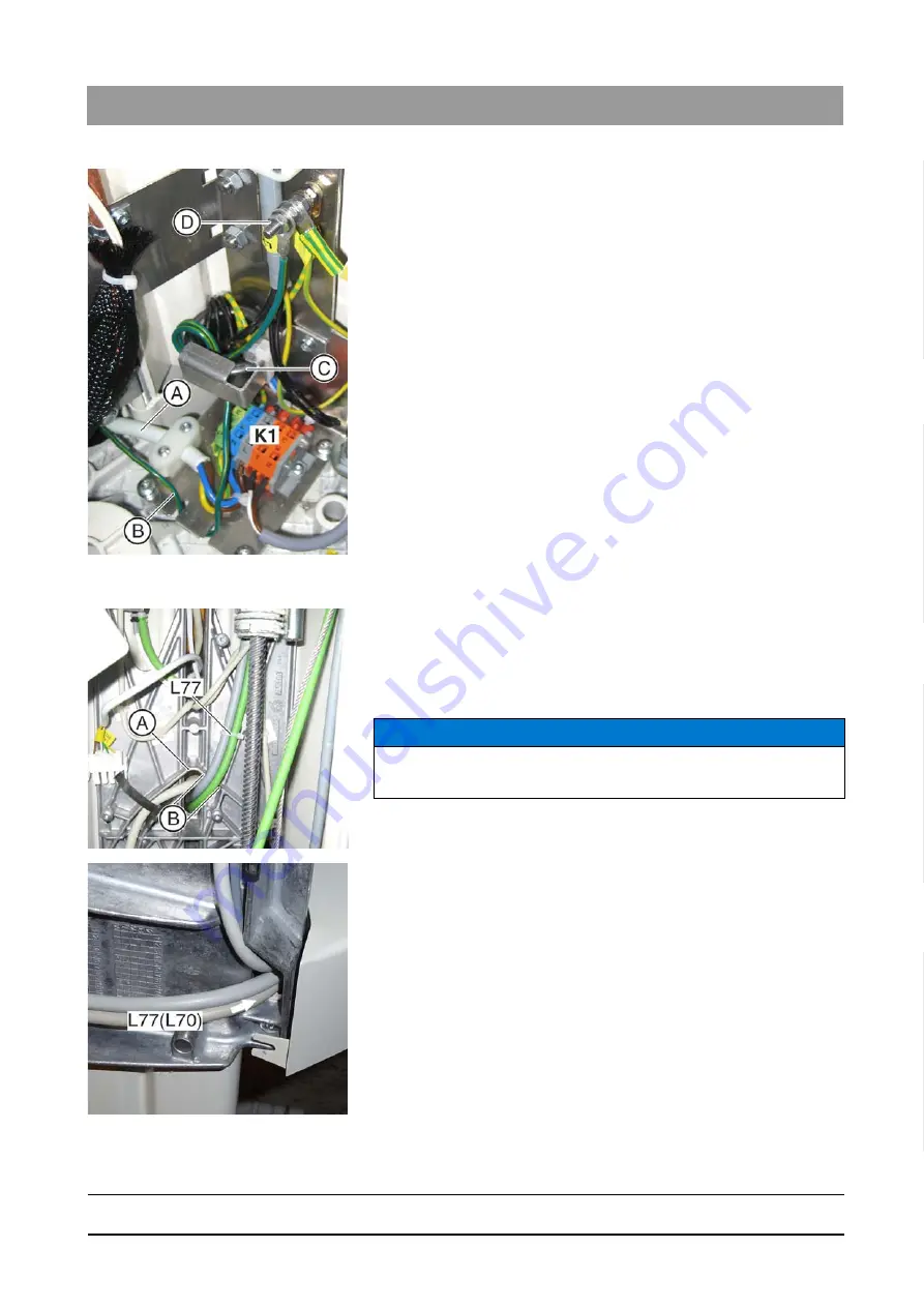
5. Screw the power cable (A) to the terminal K1 and the strain relief.
6. Route the external PE cable (B) over the mains filter plate through the
ferrite core twice (C) (two hoses).
7. Screw the external PE cable (B) down on the ground bolts (D).
9.2.5
Routing new cables in the stand
1. Lay the cable harness L77 as shown through the opening (A) on the
rear side of the stand.
The cable harness L77 branches out into an Ethernet cable
L77(L72) and a power supply cable L77(L70) on the rear side of
the board.
2. Route power supply cable L77(L70) sideways to the switch S1.
NOTICE
Operational reliability
The cable harness L77 must be fully in the notch (B)!


