background image

10 Operation light, tumbler filling, cuspidor flushing, purge 

Sirona Dental Systems GmbH

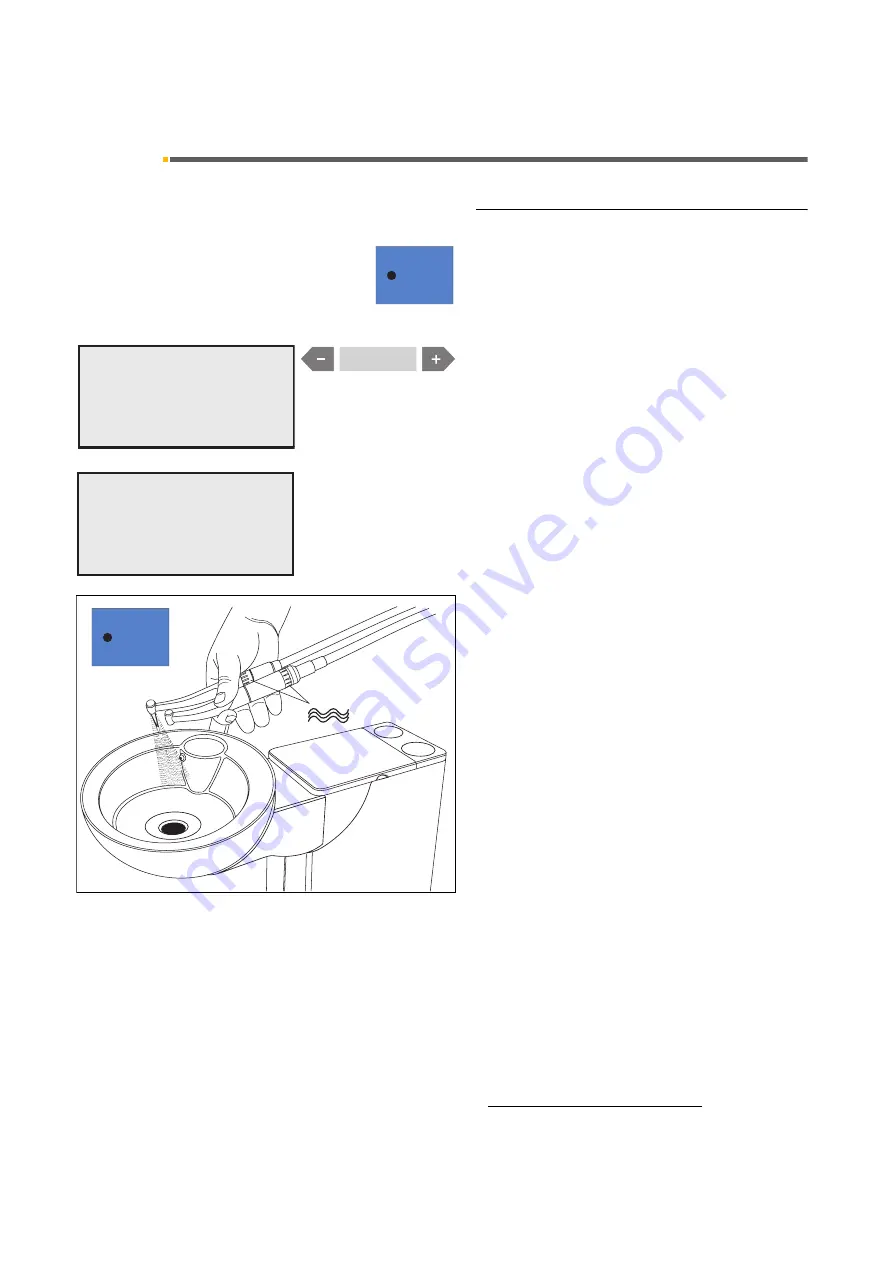
10.5 Purge / Auto Purge function (purging the water paths)

Operating Instructions C4

+

59 06 313 D 3382

54

D 3382.201.01.13.02

10.5

Purge


/


Auto Purge function (purging the water paths)

PURGE function

(only for dentist element)

The purge function enables you to flush the water paths.

To do this, press the quick setting key 1 (> 3 s) when all 
instruments are in their holders.

You will be prompted to choose between PURGE

/

APURGE 

and SANITATION

1

.

Select PURGE with the 

 or 

+

 key. PURGE must flash.

If you press quick setting key 1 briefly (< 3 s), the follow-
ing prompt will appear if all instruments are in their hold-
ers:

SELECT ITEMS FOR PURGING 

Pick up the instruments you want to flush and hold them 
above the cuspidor.

The maximum water flow must be set on the instru-
ments.

Press quick setting key 1 again


(< 3 s), the instruments 

are then purged one after the other. 

The purging time in seconds set previously in the Mode 
dialog (11.14) runs down for each instrument individu-
ally.

An audible signal sounds after the last instrument has 
been flushed.

Finally place the instruments back in their holders.

1

A

SELECT MODE
PURGE / APURGE / SAN

SELECT MODE
PURGE / APURGE / SAN

1. The SANITATION function is described in the instructions 

“Care and Cleaning by the Practice Team”.

A

SELECT ITEMS
FOR PURGING

SELECT ITEMS
FOR PURGING

max.

1

Summary of Contents for C4+ Cart

Page 1: ...b QH l f...

Page 2: ...er the installation of your treatment center Separate Operating Instructions with corresponding instructions for care are enclosed with the dental instruments SIROLUX FANTASTIC monitor Cerec Chairline...

Page 3: ...25 6 3 Selecting the chair program 26 7 Program selection 27 7 1 Safety 27 7 2 Program selection 28 7 3 MOVEMENT STOP 29 8 Patient positions 30 8 1 Flat headrest 30 8 2 Articulated headrest 30 8 3 Mul...

Page 4: ...DED 59 11 9 Mode BOWL FLUSH ON S YES NO 59 11 10 Mode CUP FILL ON S YES NO 59 11 11 Mode WHITE BALANCE only with an integrated SIROCAM 3 60 11 12 Instrument settings via Mode dialog REMOVE INSTRUMENT...

Page 5: ...ssistant element PC 94 14 10 Switching between VIDEO mode and PC mode 96 14 11 SIVISION3 second monitor function without SIROCAM3 SIROCAM C 98 15 CEREC Chairline Option 99 15 1 CEREC Chairline 99 16 E...

Page 6: ......

Page 7: ...rmed including statements concerning any modifi cations of the rated parameters or of the operating ranges if applicable as well as the date name of orga nization and signature Modifications of the sy...

Page 8: ...kers The workstation includes strong magnets which can affect cardiac pacemakers of patients users and techni cal personnel Therefore pease pay attention to the safety information on pages 7 and 57 Tr...

Page 9: ...s make sure that the system is subsequently flushed with an adequate amount of water Patient chair Please observe the maximum load capacity of the chair of 135kg according to EN ISO 6875 tested with a...

Page 10: ...tions applicable in your country Within the European Economic Area this product is sub ject to Directive 2002 96 EC as well as the correspond ing national laws This directive requires environmentally...

Page 11: ...trical shock Type B applied parts except CEREC 3D camera SIROCAM 3 SIROCAM C Type BF applied parts Degree of protection against ingress of water Ordinary equipment not protected The foot switch has an...

Page 12: ...on system automatic separator wet suction 10 Patient chair option folding armrest 11 Holder 1 SPRAYVIT in the dentist element 12 Holder 2 and 3 Electric motor highspeed hand piece burr drives 13 Holde...

Page 13: ...m automatic separator wet suction 10 Patient chair option folding armrest 11 Holder 1 SPRAYVIT in the dentist element 12 Holder 2 and 3 Electric motor highspeed hand piece burr drives 13 Holder 4 3rd...

Page 14: ...stem automatic separator wet suction 10 Patient chair option folding armrest 11 Holder 1 SPRAYVIT in the dentist element 12 Holder 2 and 3 Electric motor highspeed hand piece burr drives 13 Holder 4 3...

Page 15: ...ears when the amalgam rotor needs to be replaced DESINF is flashing when DENTOSEPT P must be refilled A appears when user A is selected B appears when user B is selected Mode key with keys for program...

Page 16: ...n burr drives Chip blower on burr drives Counterclockwise rotation for electric motor Instrument light ON OFF Pressing this key for some time displays the light inten sity settings dialog Mouth rinsin...

Page 17: ...uced light intensity 8 000 lux for composite fillings SIROLUX operation light ON OFF for normal light intensity 24 000 lux Pressing this key for a while displays the light intensity settings dialog OP...

Page 18: ...air functions gray keys for manual chair settings Tilt backrest backward or forward Height adjustment down up Additional functions of the control panel video keys NOTICE i Apart from the previously de...

Page 19: ...2 19 4 2 Control panel on the assistant element Control panel Main functions dark blue keys Mouth rinsing position chair program with memory function freely programmable Chair program 0 Entry exit pos...

Page 20: ...or flushing ON OFF X ray image viewer ON OFF for SIVISION 3 also WHITE SCREEN activation Treatment center sanitation This key can be used to start the treatment center sani tation program see instruct...

Page 21: ...eaning by the Practice Team Sanitation takes approx 24 hours Main switch Switch ON the main switch l During power up the treatment center automatically performs a self test CAUTION For safety reasons...

Page 22: ...by the service techni cian after completion of maintenance work CAUTION The dental chair has a maximum load capacity of 135kg according to EN ISO 6875 tested with a four fold safety factor according t...

Page 23: ...way foot control plate With cursor control enabled Mode dialog 11 8 A to the front cursor upward B to the back cursor downward C to the left cursor to the left D to the right cursor to the right Curs...

Page 24: ...r program keys 1 and 2 2 When you pick up an instrument or activate any of the instruments the cursor jumps to the horizontal navigation path position between 1st and 2nd row of keys in the instrument...

Page 25: ...switch to the left C cursor to the left Swing foot switch to the right D cursor to the right Cursor navigation along the marked path and release of the corresponding key function Instrument start The...

Page 26: ...he spray and chip blower keys in the first in strument block If the cursor is in the quick setting key column at the very left it also jumps to a position between the spray and chip blower keys in the...

Page 27: ...eadrest if available collides with an obstacle The swivelable cuspidor is swiveled in during chair movement The assistant element is pushed upward or down ward by an obstacle At the same time a double...

Page 28: ...on 1 or 2 Changing the factory settings When programming the patient positions you can preset whether the operation light should switch OFF or ON in the different chair programs 0 S 1 or 2 see page 36...

Page 29: ...ows By pressing one of the chair related keys on the dentist or assistant element By actuating the 4 way foot control By pushing the 4 way switches on a motorized headrest in any direction All movemen...

Page 30: ...the underside of the head cushion 2 which could affect a nearby cardiac pacemaker Therefore please avoid bringing the magnet in close proximity of a cardiac pacemaker of a patient user or technical p...

Page 31: ...atient s height This simplifies all subsequent work with the MultiMotion considerably since readjust ment to the patient s height can thus be omitted when changing over from mandibular to maxillary tr...

Page 32: ...nd tilt The MultiMotion enables rotation of the patient s head about the longitudinal axis of his body as well as lateral tilting of his head The MultiMotion is set to the desired position as follows...

Page 33: ...NOTICE i The children s head pad D is not included in the scope of supply however is available from your dental dealer DANGER The children s head pad D contains a strong mag net on its bottom side Thi...

Page 34: ...hair movements manually with the keys in the right block on the dentist element control panel Backrest tilt You can tilt the backrest also with the 4 way foot control on the chair base Lever to the le...

Page 35: ...lting the headrest Tilt the headrest backward forward by pushing the upper 4 way switch at the back of the headrest to the left right Backrest tilt You can tilt the backrest with the lower 4 way switc...

Page 36: ...tch on or remain off when the chair reaches the programmed treatment position you must switch the lamp ON or OFF now This setting is then also pro grammed CAUTION In order to avoid damage to the denti...

Page 37: ...nt is 2kg 4 4 lbs Dentist element C4 Cart The maximum load of the dentist element C4 Cart is 2kg 4 4 lbs CAUTION Risk of toppling over Move cart slowly and only on even floors without any obstacles CA...

Page 38: ...ure that the patient or the patient chair does not under any circumstances come into contact with the support arm or the dentist element 9 2 General instrument functions Spray You can switch the spray...

Page 39: ...ssed an air jet escapes from the nozzle of the burr instrument C foot switch With a C foot switch the cursor jumps directly between the spray and chip blower keys when you pick up an instrument When y...

Page 40: ...ate the foot switch briefly 1s forward or backward At the values of 200 20000 and 40000 the green LED in the corresponding key lights up When you press and hold down a key for 0 5s you adjust the spee...

Page 41: ...onding motor must have been picked up before 9 4 Highspeed handpiece Starting the highspeed handpiece When you pick up the highspeed handpiece 0 bar or PSI according to the presetting in Mode dialog 1...

Page 42: ...When you press a key whose value is the value shown on the display for 0 5s the intensity is increased When you press a key whose value is less than the value shown on the display for 0 5s the intensi...

Page 43: ...ot switched on DANGER After changing hoses press the water button of the SPRAYVIT repeatedly until water comes out Only then can you begin treatment 9 7 Saving the instrument programs The factory set...

Page 44: ...1 13 02 9 8 Placing treatment instruments in their holders A ball stopper for an unoccupied instrument holder comes with the dentist element Plug the ball stopper 1 into the unoccupied instrument hold...

Page 45: ...r it is attached to the drive 10 Only then is proper op eration of the pump guaranteed The safety cap is sup plied with every one way pump Pump hose set The peristaltic pump hose set 2 is a disposable...

Page 46: ...emitted by this instrument may be haz ardous and may never be directed to the eyes of any per son even if this person wears goggles with protective lenses The light may be directed exclusively to the...

Page 47: ...being treated with any medicine which increases one s sensitivity to light including methox salene and chlorotetracycline Any persons who have in the past suffered from retinal or eye lens disorders o...

Page 48: ...e 4 Status LEDs 5 Glare shield 6 ON OFF switch 7 Function button Operating modes The Mini L E D has three different modes To select the desired menu press the function button 4 1 Status LED The status...

Page 49: ...from 0 to 1100 mW cm or from 0 to 2000 mW cm with the optional booster light guide dia 5 5 mm Full power during 10 seconds LED 4 4 shows your selection Handling After you switch on the treatment cente...

Page 50: ...The end of the cycle is also indicated by an audible sig nal You may interrupt the cycle at any time though by lightly pressing the ON OFF switch Technical data 6 General technical data Model Mini L E...

Page 51: ...th reduced brightness 8000 lux You can toggle directly between the intensities by press ing the two keys alternately When the light is ON the green LED in the correspond ing key is illuminated Operati...

Page 52: ...he tumbler filling key 10 3 Tumbler filling with automatic sensor control Special equipment not available in all countries Functioning of the automatic sensor control With this tumbler filler the auto...

Page 53: ...tumbler brief ly and then put it back again The Mode dialog CUP FILL ON S YES NO must be set in such a way that NO flashes Hydrocolloid connection is not possible if tumbler filling with automatic se...

Page 54: ...key 1 briefly 3 s the follow ing prompt will appear if all instruments are in their hold ers SELECT ITEMS FOR PURGING Pick up the instruments you want to flush and hold them above the cuspidor The max...

Page 55: ...in the sanitation bowl and the treatment center can be switched off On the next day the APURGE function is automati cally performed again on all of the instruments re maining in the sanitation bowl as...

Page 56: ...s Press quick setting key 1 again 3 s the instruments are then purged one after the other The purging time in seconds set previously in the Mode dialog 11 14 runs down for each instrument individu all...

Page 57: ...d deactivated again by pressing the and keys simultaneously The key lock affects the entire control panel of the dentist element NOTICE i The key lock can be deactivated only as described abo ve Switc...

Page 58: ...START STOP For service engineers only 11 5 Mode FC CONTROL MODE ON OFF VARIABLE Direct starter or speed controller foot switch Presetting of the foot switch control mode for the instru ment start With...

Page 59: ...OOT CONTROL NORMAL EXTENDED Switching the cursor on off If you want to control the treatment center only manually you can switch the cursor control off The then differing functions of the relevant foo...

Page 60: ...ed the last time USER is displayed in bold type If the factory settings are valid HOME is displayed in bold type The selected item is flashing Select USER with the keys USER starts flashing Set the sl...

Page 61: ...result 11 12 Instrument settings via Mode dialog REMOVE INSTRUMENT This Mode dialog enables the following settings Instrument light voltage and Maximum torque of SL motors Setting the instrument light...

Page 62: ...orque at speeds 15 000 rpm If No is flashing The running smoothness of the motor will be higher at speeds 15 000 rpm NOTICE i The new setting becomes effective only after the corre sponding motor is r...

Page 63: ...X WITH CFS YES NO This dialog has no function in connection with the Mini L E D curing light Set NO 11 18 Mode SUCTION WITH CFS YES NO Interrupting or restarting the suction flow with the 4 way foot c...

Page 64: ...SION 3 If ON is flashing You can use the A B key to switch between VIDEO mode and PC mode after picking up the SIVISION 3 camera If OFF is flashing You cannot use the A B key to switch between VIDEO m...

Page 65: ...element is not posi tioned above the patient when the chair moves upward on contact with the patient a safety switch stops the movement Removing a handpiece rack with closed suction hand piece holders...

Page 66: ...ly remove the suction cannula from the patient s mouth If the unit has no second saliva ejector hose for the sur gical cannula the thick suction hose must be used for surgical aspiration To insert a s...

Page 67: ...strument that has been picked up you may switch the instrument light on or off Its brightness is set to an optimum value and cannot be changed The instrument light switches on when you activate the SP...

Page 68: ...moves back to its starting position before the chair moves to the pro grammed position When you press a key for the individual adjustment of the chair i e height adjustment up down or backrest tilt b...

Page 69: ...ing level of 95 see instructions Care and Cleaning by the Practice Team A continuous sound indicates that the rotor is full and no longer functioning properly An intermittent sound indicates a system...

Page 70: ...orm sanitation Remove the cover behind the cuspidor and fill in 1 liter of DENTOSEPT P The filler trough should always be kept clean Always make sure that no tap water enters the filler trough For reo...

Page 71: ...stem overview of SIVISION 3 59 06 313 D 3382 D 3382 201 01 13 02 71 14 SIVISION 3 14 1 System overview of SIVISION 3 SIVISION on the lamp support tube Rotatable swivelable Monitor on tray arm Rotatabl...

Page 72: ...movements of the dental treatment chair and or operation of the cuspidor Swivel the monitor out of the collision area if necessary SIVISION 3 monitor versions 15 Monitor with glass pane 19 Monitor wi...

Page 73: ...s C4 14 2 Camera versions 59 06 313 D 3382 D 3382 201 01 13 02 73 14 2 Camera versions SIROCAM 3 Integrated 4 view image memory 3 fold adjustable focusing range Titanium case SIROCAM C Integrated 4 vi...

Page 74: ...f The camera heats up during operation To prevent overheating of the camera the camera must be put down for a time interval t2 3 min after an operat ing time of t1 1 min The camera will heat up even w...

Page 75: ...cover with its paper side face down and insert the camera with the optical system downward into the cover 2 Pull off the upper protective foil with the blue stripe 3 Then pull off the backing paper 4...

Page 76: ...care The camera illuminates the tooth areas to be imaged with 6 white light LEDs 1 These are arranged around the single lens optical sys tem 2 The LEDs and the lens are protected by a scratch proof an...

Page 77: ...aper 4 Finally stretch the hygienic protective cover over the camera from front to rear CAUTION For optimum image quality there must not be any folds in the transparent area of the cover above the len...

Page 78: ...LIVE IMAGE This mode remains active even after you switch OFF and back ON the treatment center SWITCHING TO VIDEO MODE A B key on the control panel Only with camera picked up and activated manually o...

Page 79: ...eo mode In this version the SIROCAM 3 SIROCAM C intraoral camera is installed in holder 5 of the dentist element or in an additional holder on the dentist element The camera can be controlled with the...

Page 80: ...ll images con secutively indexed with I II III and IIII A 5th view shows a QUAD IMAGE in which these 4 still images are tiled on the screen Picking up the camera If a STILL IMAGE or QUAD IMAGE was dis...

Page 81: ...ch with instru ments in place or camera picked up With C foot switch also left foot switch button only with camera picked up NOTICE i If the camera is in the LIVE IMAGE mode the LIVE IM AGE is stored...

Page 82: ...ments in place or camera picked up With C foot switch also right foot switch button only with camera picked up Toggling between a QUAD IMAGE and a SINGLE IMAGE When you switch to a SINGLE IMAGE the i...

Page 83: ...or QUAD IMAGE BLACK SCREEN or WHITE SCREEN remain displayed SWITCHING TO THE NEXT IMAGE WITH THE CUR SOR Special function only with cursor The cursor is in the chair programs key block level 1 With t...

Page 84: ...NO flashes or X ray image viewer and WHITE SCREEN on the SIVISION monitor ON OFF if YES flashes NOTICE i WHITESCREEN NO should be selected if an X ray im age viewer is installed If no X ray image vie...

Page 85: ...ional scope of the PC can be used in this mode If the camera is the active instrument VIDEOCAM and the operating mode PC MODE appear on the dis play Picking up the camera The LIVE IMAGE window opens T...

Page 86: ...p blower Electric motor CCW rotation Instrument light Quick setting keys 50 and 1 Cursor forward if the cursor is between the spray and chip blower keys with C foot switch only if the camera is in its...

Page 87: ...this purpose a patient must be registered in SIDEXIS VIDEXIS Manually or by cursor using the foot switch with instru ments in place or camera picked up With C foot switch also left foot switch button...

Page 88: ...OFF if YES flashes NOTICE i WHITESCREEN NO should be selected if an X ray im age viewer is installed If no X ray image viewer is in stalled select WHITESCREEN YES BLACK SCREEN 100 quick setting key o...

Page 89: ...rsion the SIROCAM 3 SIROCAM C intraoral camera is installed in holder 1 or 2 of the assistant ele ment It is operated exclusively with a separate foot button in the chair base and the camera button Pi...

Page 90: ...mage number I appears in the upper right corner of the image When you touch the foot button again briefly a LIVE IMAGE reappears To freeze the next STILL IMAGE briefly touch the foot button again Imag...

Page 91: ...tton The image number of the selected image appears in the upper right corner of the image When you briefly press the camera button the se lected image is displayed on the screen as a single STILL IMA...

Page 92: ...element video Operating Instructions C4 59 06 313 D 3382 92 D 3382 201 01 13 02 DELETING ALL IMAGES from the camera memory With a QUAD IMAGE displayed and the camera picked up Press and hold down the...

Page 93: ...ack the camera If a LIVE IMAGE was displayed a BLACK SCREEN appears A STILL IMAGE or a QUAD IMAGE remains dis played WHITE SCREEN To activate a WHITE SCREEN the camera must be placed in its holder Whe...

Page 94: ...PC connection and SIDEXIS VIDEXIS To use the PC mode SIDEXIS VIDEXIS must be open The PC mode must be activated on the PC See section 14 10 Switching between VIDEO mode and PC mode Picking up the cam...

Page 95: ...59 06 313 D 3382 D 3382 201 01 13 02 95 SAVING A STILL IMAGE IN SIDEXIS VIDEXIS Save the displayed STILL IMAGE by pressing the foot button for some time 1s when the camera has been picked up A LIVE I...

Page 96: ...ement and a connected PC The system can be used in two operating modes Video mode The video image from the camera is directly dis played on the SIVISION monitor PC mode The video image is processed on...

Page 97: ...you switch off the PC The SIVISION monitor must also be set to video mode S Video Port see monitor operating instructions Switching to PC mode Right click the Siucom icon in the Systray usually in th...

Page 98: ...not already used for relay functions key if not already used for relay functions All quick setting keys 100 50 and 1 Cursor forward if the cursor is between the spray and chip blower keys Cursor forwa...

Page 99: ...e refer to the CEREC Chairline Operating Instructions REF 60 46 028 and Operator Manual REF 59 56 458 CEREC Chairline foot switch A Bluetooth radio module for transmitting the CEREC foot switch signal...

Page 100: ...addi tional equipment connected to the treatment center also complies with the requirements of EN1717 DIN1988 Technical data and requirements Connected equipment is treated with disinfected wa ter if...

Page 101: ...he headrest cover over the headrest and fasten it as illustrated 16 3 Seat cushion C Extra equipment The back part is fastened with a Velcro closure and can be removed Covering material 100 cotton The...

Page 102: ...e state your address and the serial number of the chair see Installation Report Warranty Passport To connect the adapter to the cuspidor proceed as fol lows Pull out the tumbler outlet 1 turning it sl...

Page 103: ...ions C4 16 6 Tray extra equipment 59 06 313 D 3382 D 3382 201 01 13 02 103 16 6 Tray extra equipment NOTICE i Maximum load 4 kg NOTICE i Maximum load 1 kg For further details please refer to the opera...

Page 104: ...t control panel To view intraoral dental images the anti glare film 1 must first be attached with two clips Then fasten the intraoral dental images with the third clip over the cut out 16 8 X ray imag...

Page 105: ...13 02 105 16 9 X ray image viewer on the tray Extra equipment This X ray image viewer is switched ON or OFF using the illustrated key on the dentist or assistant element control panel To view intraora...

Page 106: ...tion and maintenance In order to guarantee the operational safety and reliabil ity of your treatment center and to avoid damage due to natural wear yearly inspection and maintenance must be performed...

Page 107: ...ction as well as mea surements of the protective ground wire connections and the equivalent leakage currents The inspections and measurements to be performed are specified in the Maintenance Manual Th...

Page 108: ...17 Maintenance Sirona Dental Systems GmbH 17 4 Maintenance Manual Operating Instructions C4 59 06 313 D 3382 108 D 3382 201 01 13 02...

Page 109: ......

Page 110: ...a p d e OMMNJOMMS p W m d a PPUOKOMNKMNKNPKMO MSKOMMT KJk KW NMU PUV f p a p d e rp W W c PN SQSOR _ d K K p a p ii QUPR p a I p NMM I k OUOTP rp p PORM o a J r R j I l iRi RvS l k RV MS PNP a PPUO t...

Reviews: