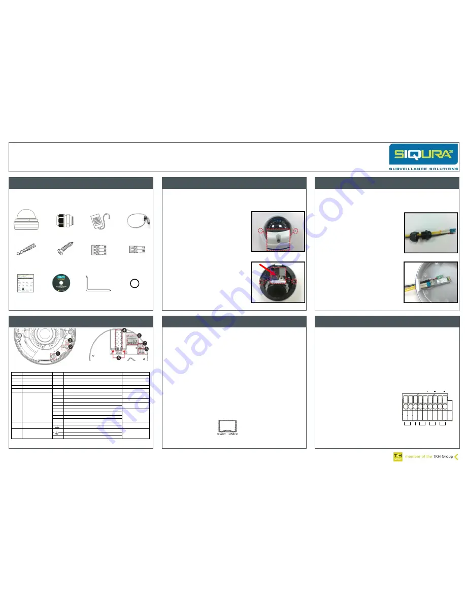
Connect to power and network
Siqura FD820M1(IR)-SFP
High-definition fixed dome camera with SFP interface
Quick Start Guide
© Siqura B.V. 2014
Version 2.0 (131211-2)
FD820M1(IR)-SFP QSG (MW10)
Connector overview
Figure 6 FD820M1(IR)-SFP Printed Circuit Board (PCB) connectors
Check package contents
Figure 1 FD820M1(IR)-SFP package contents
Verify that your FD820M1(IR)-SFP package contains the following
items.
FD820M1-SFP camera
Conduit
Siqura Product CD
Self-tapping
screws (x5)
2-Pin connector
Plastic screw
anchors (x5)
Quick Start Guide
12 Vdc Power adapter
Install the camera
The fixed dome camera can be installed directly on a wall or ceiling.
Make sure that the provided surface has sufficient strength to support the
camera.
1.
Make sure that the provided surface has sufficient strength to support
the camera.
To remove the camera from the dome
housing
1.
Release the two screws indicated in
figure 2, and then open the dome
cover.
2.
Press both sides of the inner cover
and remove it.
3.
Loosen the two camera-fastening
screws (figure 3) and detach the
camera housing.
To mount the dome housing
Attach the dome housing to the wall
or ceiling with the supplied screws
and screw anchors. If necessary,
replace the screws with mounting
screws that are more appropriate for
the mounting surface.
To connect the cabling
1.
Run the cables through the cable
gland (figure 4).
2.
Thread the cables through the
conduit entry (figure 5).
3.
Connect the cables to the camera
body as indicated in the following
sections.
4.
Place the camera body back onto the
camera housing and tighten the
camera-fastening screws.
5.
Fasten the gland body to the
side/back conduit entry.
Figure 4
Connect audio and alarms
3-Pin connector
Figure 5
www.siqura.com
www.tkhsecurity-usa.com
No.
Connector
Pin
Definition
Remarks
1
BNC
-
For analogue video output
2
Micro SD card slot
-
For video recording storage
3
Default button
-
Press the button to restore the defaults.
4
SFP Network
-
For SFP Cable connection
5
Network LEDs
-
Network connection and activity indication
6
Alarm & Audio I/O
1
Audio In (L)
Line In
2
Audio In (R)
3
GND
4
Audio Out (L)
Line Out
5
Audio Out (R)
6
Alarm Out +)
Alarm connection
7
Alarm Out (-)
8
Alarm In (+)
9
Alarm In (-)
7
Power connector
DC 12 V
12 V
Power
Power connection
GND
8
Power connector
AC 24 V
AC1
Power-1
Power connection
GND
AC2
Power-2
Table 1 FD820M1(IR)-SFP Printed Circuit Board (PCB) connectors description
Attach cabling
Figure 2
2aconne
ctor
Figure 3
Note:
I
nsert the SD card into the Micro SD
card slot before you power on the camera. If
the camera is already powered on, reboot the
camera after the SD card is inserted.
Connect power and network cables to the camera as described in
figure 6 and table 1.
To connect to network
Connect one end of the SFP cable to the SFP connector of the camera
(see figure 6), and connect the other end of the cable to the network
switch.
Note:
Check the status of the link indicator and activity LEDs. If the LEDs
are unlit, check the LAN connection.
A green LINK light indicates a good network connection.
The orange ACT light flashes to indicate network activity.
To power on the camera
Plug the 12 Vdc or 24 Vac cable into the power terminal block.
Figure 7 ACT and LINK network LEDs
If microphones and speakers are implemented, the camera can be
used to provide a two-way audio channel.
Connecting an alarm device to the camera input can trigger an output
action to occur based on contact closure settings.
To connect audio
Connect the audio input and output connectors to the terminal block
on the back of the camera (figures 6 and 8).
Via the camera’s Audio webpage, you can set audio streaming to full-
duplex, half-duplex, simplex, or you can disable audio streaming.
To connect an alarm device
Connect the alarm relay connectors
to the terminal block on the back
of the camera (figures 6 and 8).
Use the Application, Motion
Detection, and Tampering
webpages to configure the alarms
as desired.
1 2 3 4 5 6 7 8 9
Audio
In
GND Audio
Out
Alarm
Out
Alarm
In
L
R
L
R +
+
Figure 8 Audio and alarm I/O terminal block
Attach the power, network, audio, and alarms cables to the back of
the camera.
Power cable
Security torx
Rubber ring


