background image

53 

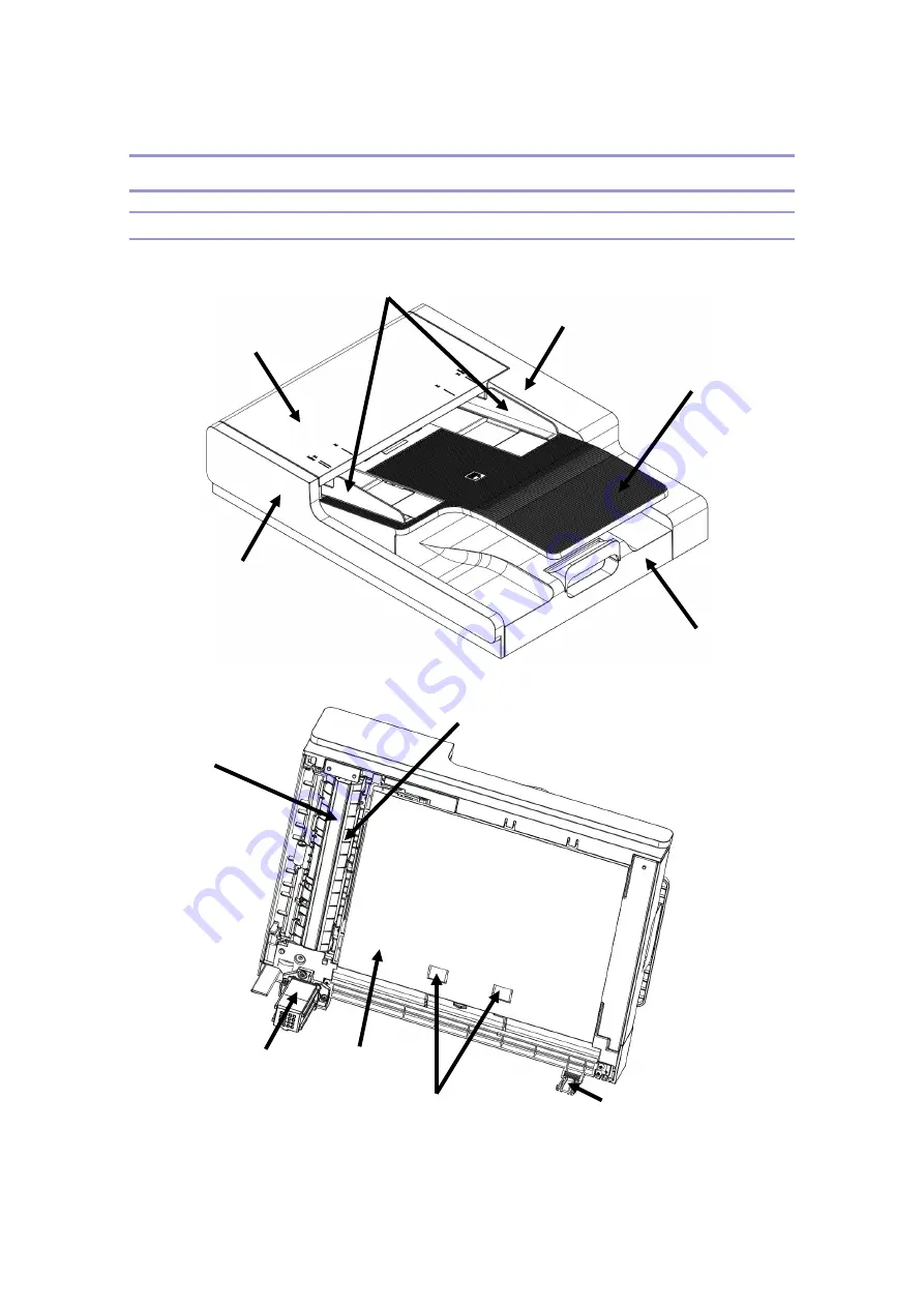
ADF (Auto Document Feeder) 

Overview 


Auto Document Feeder(called ADF afterwards) is a device for scanning the original by 

ADF front cover 

ADF Front cover 

ADF side fence 

ADF rear cover 

ADF doc. tray 

ADF main frame 

ADF upper guide 

ADF pressure plate 

ADF left hinge 

ADF back 

plate 

ADF A3 roller 

ADF right hinge 

Summary of Contents for M611

Page 1: ...FIELD SERVICE MANUAL M611 M616 M612 M617 CS 2014 6 13 CE Confid ential...

Page 2: ...Unpacking and Check the Enclosure 5 Optional Tray 6 Image Cartridge 7 Maintenance 10 PM Preventive Maintenance 10 Customer Changeable Items 10 Other Maintenance Items 10 Detailed Description 11 IMAGE...

Page 3: ...t 28 Paper Feeding 29 Overview 29 Paper Tray Layout and Mechanism 29 Pickup Unit Layout and Mechanism 30 Paper Tray Open Close Mechanism 31 Paper Feed Transport Mechanism 32 MPT Multi purpose Tray 38...

Page 4: ...Functins of User Interface Control Card UICC 69 View and Important Functins of FAX 73 View and Important Functins of LVPS 75 View and Important Functions of HVPS 79 Replacement and Adjustment 89 Befo...

Page 5: ...y 117 Removing Transport Unit of Optional Tray 119 Removing Optional Acufeed Unit 122 Register Guide A ssy 126 Removing Register Roller 127 Paper Exit Unit 129 Duplex Unit 130 Removing Duplex Unit 130...

Page 6: ...r Drive Assembly 157 Troubleshooting 158 Error Messages and Error Codes 158 Service Error Codes 158 Messages for User Intervention and Paper Jam 165 Paper Jam 170 Service Menu 172 Diagnostic Menu 172...

Page 7: ...asic composition 2 stack optional tray 500 sheets MPF 50 sheets Machine Spec Commercial Class PINETREE M611 616 PINETREE S M612 617 Print Speed A4 40ppm 47ppm Speed for 1st Page Less than 10 sec Resol...

Page 8: ...clusive Size W X D X H 383X386X515 mm Paper Spec Trays Load per Media Paper Size Base Tray Plain Paper 500 sheets Label 50 sheets Thick 50 sheets A4 A5 JIS B5 Folio Letter Legal Executive Statement Op...

Page 9: ...Gear Arm Pivot Assy 1EA 6 BKT Accufeed PR 1EA Frame External Unit 1 Frame Assy 3EA MO 2 PR 1 2 Exterior Cover 4EA Paper Feed Tray Unit 1 Cassette Tray 1EA 2 Cover Tray 1EA 3 Side Fence _ Left 1EA 4 S...

Page 10: ...o Installation Installation Condition Environment The machine should be installed on the following places Where good ventilation is provided Where no obstacle is placed within at least 8 cm on the rig...

Page 11: ...the machine 3 Check the machine and the accessories Enclosure List No Part No Description QTY Remarks 1 Basic Tray Unit 1 250 sheets 2 LA258058 AC Power cord 1 220V 3 L0025703 USB cable 1 4 M0134105 Q...

Page 12: ...the tray support 2 Pull out the feed unit 3 Hold the both ends of the support and place it where the machine is installed 4 Re install the feed unit Push it to fit into the machine 5 Lift up the machi...

Page 13: ...chine must be off when installing the optional tray on or removing it from the machine Image Cartridge Installation 1 Open the front cover on the upper side 2 Hold the handles of the cartridge and lif...

Page 14: ...the cartridge by bare hands 4 Hold the cartridge by the handles and shake it lightly so that the toner can be evenly distributed 5 Hold the cartridge by the handles and align the guides of both sides...

Page 15: ...9 7 Close the front cover Make sure both sides of the cover clicks shut Check if MPT multi purpose tray is also closed Closing the front cover with the MPT cover open may cause malfunctions...

Page 16: ...he life cycle values are subject to change upon the envronment and printing conditions Other Maintenance Items Class Model Name Parts Life Cycle M611 612 M611 M612 M616 M617 Fuser 120K Tray Acufeed ro...

Page 17: ...11 Detailed Description IMAGE PROCESS Electric Charge 1540V is supplied from HVPS to Charge roller and around 900V is charged on the drum surface by this Laser Exposure...

Page 18: ...tential on that area is dropped by around 300V making latent images Development At the exposure step the toner charged around 550V thru Deveoper Roller and Doctor Blade is attached on the latent image...

Page 19: ...ed with around 2000Vpulls and transfer the toner which was making images on the drum to the paper without settlement yet Cleaning After trasferring the toner to the paper the little remainder of the t...

Page 20: ...14 MFP Overview MFP Components...

Page 21: ...eloper Roller 8 Doctor Blade 9 Add Roller 10 Paddle Roller 11 Mid Roller 12 Maual Tray Pickup roller 13 Manual Tray Friction Pad 14 Tray1 Pickup roller 15 Tray1 Friction Pad 16 Tray1 base plate 17 Reg...

Page 22: ...16 Paper Path 1 Output bin 2 Manual Tray 3 Base Unit Tray 4 Optional Tray Unit 5 Duplex Unit...

Page 23: ...polygon mirror motor M3 Vent Fan Remove the heat around Fuser Switch SW1 Power Supply the power to the machine If it is off no power is supplied to the machine located at lower rear and right side SW...

Page 24: ...ations directly and indirectly thru a different control board PCB2 PDU Power supply unit Supply AC power to Fuser lamp and optical heater and DC power to the system Solenoid SOL1 Tray Feed Control pic...

Page 25: ...ere is one main motor in the machine and the rotation power is delivered to a set of gear consisting of many gears drives developer drum Fuser manual tray Fuser duplexer Register roller and pickup rol...

Page 26: ...Opened As you open the front door of the machine the link to the font door is moving to the 1 direction Upon the moving link the lever 2 consequently moves and the cartridge is released by the oldham...

Page 27: ...moving the Paper Jam at Fuser 1 When removing the paper jam stucked in rear side of Fuser Gear link is moved backward and the connections of the gears are released to remove the paper jam 2 When remov...

Page 28: ...Sync Sensor C Cylindrical Lens H 2 F Theta Lens D Polygon meter I Reflection Mirror E 1 F theta Lens J OPC Drum Laser Diode Unit Generate laser beam Collimeter Lens Change dispersed laser beam to a l...

Page 29: ...re therefore directed to return the complete laser unit to the factory or service depot when replacement of the laser unit is required LSU Information LSU Manufacturer OSS CO LTD LSU Type No SDH LSU A...

Page 30: ...Image Cartridge consists mainly of the drum cartridge and toner cartridge as shown at the above and they can be separated The drum cartridge does not have any separate chip in it while the toner cartr...

Page 31: ...g blade Charge cleaner roll Charge roll Wasted toner case Drum The drum cartridge consist mainly of a drum a charge roller a cleaning blade and a wast toner case as shown in the above image Charge cle...

Page 32: ...s toner to the add roller as shown in the above image The Doctore blade lets the toner evenly gets on the surface of the Developer roller by the Add roller Driving Drum Cartridge The drum C in the car...

Page 33: ...ntually to Idle coupler gear D in the toner cartridge The driven Idle coupler gear rotates to make the Devleoper roller Add roller and Paddle roller to rotate Voltage Supply to Drum Cartridge The Char...

Page 34: ...per roller is supplied with necessary voltage thru Developer voltage supply spring A the Add roller thru Add voltage supply spring B and Add roller contact plate as well and the Doctor blade thruDB vo...

Page 35: ...same method as Acufeed 500 Option as a paper tray can be shared with base unit of KARA S KARA S base unit has a default cassette type paper feed tray and a MPT which can load 500 sheets of A4 75gsm an...

Page 36: ...sing the tray feeding pressure 2 Pickup Motor Supply the power for the rotation of Pickup Roller and control the feeding speed by adjusting the timing 3 Driving Gear Set Acufeed Arm Assy Deliver the p...

Page 37: ...and make it straying on the same position Once closing the tray with paper loaded the structure 5 presses Bell Crank spring arm 4 and so the support of shaft pin 3 is released then Acufeed arm assy au...

Page 38: ...he transport roller and then the rest part of the paper is fed by the transport roller through Mid roller to in the base unit and complete the feed But the pickup roller rotates every time by the pres...

Page 39: ...nd the fence lever together Load the paper by stacking up to the limit line marked on the label attached on the side fence Especially one side printed paper can be classified as a special paper due to...

Page 40: ...and the fence lever together When loading the paper firstly move the rear fence and the fence lever backward all together to the most and align the paper leading edge to the separation dam and move t...

Page 41: ...is machine detects the remaining paper using the output values from the two sensors The two sensors detects 3 status and show them on the LED in the machine Sensor 1 Sensor 2 Stack Paper Full 10 100 P...

Page 42: ...detection Finger which is related to the paper size detection sensors combination of 3 switch type sensors is put in the hole of the END Fence after alignning the rear side of the paper and adjust th...

Page 43: ...37...

Page 44: ...o the paper size with the extension support unfolded not to make any gap The maximum limit of the paper stack is separately specified for postcard envelope label and special paper Components Layout of...

Page 45: ...in motor is delivered to the pickup roller in MPT Accordinly the rotation of the pickup roller allows the cam move together and the base plate goes up by stength of the spring then the pickup roller c...

Page 46: ...presence in the tray If MPT is empty the sensor flag assembled in the lower body assy return to home position by the torsion spring and blocks the path of the light emitted from the emitter and accor...

Page 47: ...nction it plays a role of upper rib for good papaer path and there is a roller installed to correct some skew 2 Front body It plays a role of guiding the paper on the paper reverse area lower part to...

Page 48: ...d to the left by an obique roller at the reverse rotation area A4 or Letter has no difference Detecting Paper Jam When a paper jam occurs at the paper reverse area in the duplex unit firstly push the...

Page 49: ...nted paper then arrives at the exit roller thru the fusing area and is fowarded to the duplex area by operating the solenoid and driving the normal reverse rotation bracket The paper transferred to th...

Page 50: ...fed from the base unit tray or MPT along with the guide path to the Register unit and delayed a little time at first due to the Register 4 sets Even though the paper is delayer owing to the Register...

Page 51: ...onents Layout of Fuser The Fuser and the paper exit area consist of the following components 1 Fusing roller 2 Pressure roller 3 Heater 4 THERMOSTAT 5 THERMISTOR 6 Separatior 7 Input guide 8 Exit guid...

Page 52: ...tomer want to within a limited range When an error occurs or power save mode is on the power for Heater will be off Preventing Overheat If the temperature of the Fusing roller goes up higher than 235...

Page 53: ...sed via cams which releases the pressure and if pulling the lever reversely to 2 direction the two rollers return to the home position When printing on the standard paper with the status of the pressu...

Page 54: ...orting these 3 Assy s OP Assy is assembled and mounted onto the front side of the whole Assy The machine size in other words the scannr thickness and the price can be reduced by using CIS instead of C...

Page 55: ...irmly gluing each other By this time the height levels of Slit glass and Contact glass should be idential to get the same image quality when scanning from flatbed and ADF Also when driving CIS it need...

Page 56: ...embly status of two parts when a skew occurs Components Layout of Drive ASSY The Drive ASSY consists of motors and brackets dampers stopping the vibration of the motor two driving gears reducing rev c...

Page 57: ...ming belt thru gear pulleys connected to the drive gears The timing belt is connected to CIS frame which is adjusted by the movement of the timing belt The CIS home position is defined by activating t...

Page 58: ...information corresponding one by one to the image of the point to the sensor which is in line towards the scanning line direction The reduction optical system of the color scanner also reflects the w...

Page 59: ...eder called ADF afterwards is a device for scanning the original by ADF front cover ADF Front cover ADF side fence ADF rear cover ADF doc tray ADF main frame ADF upper guide ADF pressure plate ADF lef...

Page 60: ...can unit and covers covering this Assy And there is hinges that enable to open or close ADF when copying booklets Components Layout of ADF Upper Cover ASSY ADF upper cover ASSY consists of Pickup Assy...

Page 61: ...sts mainly of pick roller pickup roller pickup holder and pickup shaft The life cycle of the pickup Assy is identical to ADF It is attached to the ADF upper cover and makes easy removal of the jammed...

Page 62: ...separation path sections This separation pad Assy maintain the separation force with springs compression Components Layout of Motor ASSY M0132001 Transport otor M0132001 for Feed motor M013 3151 Gear...

Page 63: ...port area is connected to the 1st scan and the 2nd scan and the feed area is connected to the tray and A3 drive Components Layout of UPPER GUIDE ASSY The PINETREE ADF has duplex copy and scan function...

Page 64: ...dust or foreign substances Components Layout of the 1st IDLE Guide ASSY This is an Assy with vertical motion roller for the original to go in for the 1st scan Identical structure with OAK MV123244 FRA...

Page 65: ...paper trasportation M013 3241 FRAME CORE M0100077 INTERVAL sensor LM505319 PRESENT sensor LM505319 top cover open detect sensor LM505319 1st scan detect sensor M013 3262 ROLLER 2ND FEED M013 3261 ROL...

Page 66: ...SY The A3 ASSY does A3 scan and copying operation with the power delivered using teh timing belt from gear pulleys among the motor assy By this time when feeding A3 install the clutch and use the powe...

Page 67: ...Functions of SOC DC1250 Read execution codes from flash memory Serial and NAND Flash and control the overall flow of the program Control the image process sections to read the original contents and p...

Page 68: ...be possible Important Fuctions of Scan Image Process Original scanning speed 1 2ms Line Color 0 6ms Line Mono Shading correction Gamma correction Halftone mode Threshold Error diffusion Pin Array 1 S...

Page 69: ...6 CIS_CLK Image data output sync clock 7 CIS_SP Line base control signal for CIS data output 8 CIS_VREF CIS VREF power input signal 9 3 3VAS CIS_VCC 10 COM2 Analog ground 11 CIS_MODE CIS MODE selecti...

Page 70: ...power 4 nSH_H SAMPLING HOLD 5 nLDEN_H Laser Diode enable signal 6 nVIDEO_H Image data signal 7 GND GND 7 SYSTEMCARD POLYGON MOTOR CN8 NO Signal Description 1 nLSU_CLK_H Criterial CLOCK to be supplied...

Page 71: ...ignal 17 VREF_K2 LD2 actinography VREF1 signal 18 COM1 GND 9 SYSTEMCARD HVPS LVPS IF CN40 NO Signal Description 1 TX_SENSING Transfer F B signal 2 TX_ENB Transfer ENABLE signal 3 TX_PWM Transfer outpu...

Page 72: ...7 WAKE POWER SAVE release signal 12 SYSTEMCARD OPTION_TRAY CN39 NO Signal Description 1 I2C_DAT Tx Rx of TRAY and DATA 2 I2C_CLK Criteria CLOCK for DATA exchange 3 NOTIFY TRAY SET detection 4 24VIN 24...

Page 73: ...42 NO Signal Description 1 24VIN 24VIN 2 24V_SW 24V_SW 24V to become F B by switch 16 SYSTEMCARD EXIT SOL CN26 NO Signal Description 1 24VIN 24V power 2 EXIT_SOL_L Paper exit solenoid ON 17 SYSTEMCARD...

Page 74: ...detection signal 5 COM1 GND 6 5V_UICC_S Sensor power 21 SYSTEMCARD INPUT_S CN36 NO Signal Description 1 INPUT_S Paper feed detection signal 2 COM1 GND 3 5V_UICC_S Sensor power 22 SYSTEMCARD SB1 SB2 _S...

Page 75: ...69 NO Signal Description 1 COM1 GND 2 ADF_Cover_SW ADF cover switch ON signal View and Important Functions of User Interface Control Card UICC Block Diagram OAK UICC 4 in 1 Block Diagram...

Page 76: ...e Wakeup button excluded 3in1 dedicated key 2 4in1 dedicated key 18 common key 8 MCU and LCD module exchanges data in 4 bit parallel type Backlight of LCD control on off using switching elements There...

Page 77: ...71 4 LED Drive Section Common Application Stutus LED Backlight LED Control 5 Buzzer Control Section...

Page 78: ...selection H Data Register L Instruction Register 3 CSB Select chips from paralle mode and series interface Low active 4 R W Read Write selection pin L Write H Read 5 E Starts data read write 6 DB4 Dat...

Page 79: ...he following Important Fuctions of HSD CX95110 The default modem speed is max 33600bps and can automatically be reduced to any proper speed when the speed needs to be limited Perform SPI communication...

Page 80: ...DIB Pin Array 1 FAX SYSTEMCARD CN2 NO Signal Description 1 FAX_CS FAX modem chip selection 2 COM1 GND 3 FAX_DI Data signal pin to Systemcard 4 COM1 GND 5 FAX_DO Data signal pin from Systemcard 6 COM1...

Page 81: ...the following 1 AC switch Open only one AC line 1 POLE type 2 Varistor When overvoltage inflows in the input section it is shorted to protect the rear circuit section 3 BRIDGE DIODE MAIN CAP Rectify...

Page 82: ...Or Equivalent CHILY 2 Heater Connector Connector No Connector Name Pin No Signal Name Images CN2 HEATER CONNECTOR 1744056 3 AMP Or Equivalent 1 HEATER_L 2 removed 3 HEATER_N 2nd pin out of total 3 pin...

Page 83: ...y nominal 47 63 Hz Voltage band nominal 220 240Vac Voltage min max 198 264Vac Non destructive Voltage 187 276Vac Input current AC DC 4 8A Input power Energy save mode Efficiency 40 or above Energy sav...

Page 84: ...ntains min 30 min operation 5 7A Maintains min 30 min operation Peak output current 6 0A 2nd inrush circuit Surge current 20A Min 50uS Total max output power 10W 140W Static mutual load change conditi...

Page 85: ...of 4 DC DC converters and 7 channels such as Charge CHG Photo Drum PD Developer unit DEV TR BL and Transfer TX TX 2 Output characteristics Static voltage method including transfer channel 3 Each logic...

Page 86: ...hen it is higher than 12 A it delivers HIGH LEVEL 8 CHG PWM Controls CHG and PD channel voltage PD channel use a zenor diode to always maintain 200V compared to GND 9 DEV PWM Controls DEV TR and BL ch...

Page 87: ...0V 20V 1000V Enable 400V 3500V Tolerance 21V 250V 700V 3 700V 2000V 10V 10V 20V 333V 3 333V 1000V 5 5 100V 22V 400V 600V 100V 600 V 3500V Rated Load 20M 1GM 20M 1GM 270M 1GM 30 M 1GM Setting Output Vo...

Page 88: ...82 3 24V Output Section...

Page 89: ...83 4 5V Output Section...

Page 90: ...84 5 AC Drive Section 6 Switching Section...

Page 91: ...85 Circuit HVPS Input Section 1 PWM Input Section...

Page 92: ...86 2 RCC Control Drive Section...

Page 93: ...87 3 High Power Output Section 4 TX SENSING...

Page 94: ...88...

Page 95: ...rn the main switch off and unplug the power cord and network cables from the machine When disassembled take care of missing various bolts Refer to the harness path and process the same order when re a...

Page 96: ...careful of breaking any of 4ea hooks inside the cover Left Cover 3 Remove the rear side door and cover from the base unit 4 Open the front cover to release the lock of a hook at the bottom side of the...

Page 97: ...ful of 8ea of hooks at inside of the cover Right Cover 1 Remove the rear side cover from the base unit 2 Open the front cover to release the lock of a hook at the bottom side of the machine Lift up th...

Page 98: ...move the side covers 3 Remove 2ea of bolts at the upper and lower sides of the Operation Panel separate the harness connected to CN30 connector in the main board and separate the control panel from th...

Page 99: ...en re assembling Front Door 3 Open the front door A 4 Release 3ea of hooks locked at the left and right side to separate the links 5 Push the left door hinge to the left to separate it from the frame...

Page 100: ...om the base unit 8 Remove the Operation Panel 9 Remove the 2 bolts at the left top of the frame 10 Remove the 3 bolts at the right side of the frame and then lift up the top cover to separate it from...

Page 101: ...eyes due to the laser beam Removing Laser Unit Make sure the main power switch is off and the power cord is unplugged before disassembling or adjusting the laser unit 11 Open the front door 12 Remove...

Page 102: ...96 6 Remove 4 screws of the laser unit 7 Remove the laser unit from the base unit The base unit with the laser unit removed...

Page 103: ...lation of the laser unit 1 Place the laser unit onto the FRAME 2 Position the laser unit on the frame using skew JIG A before completely fixing it and then tighten it with 4 screws Order of screwing 1...

Page 104: ...before installing the top cover Alignment of Laser Optical Housing Unit In case of replacing and mounting the laser unit with a new one align the laser unit upon the below processes A Laser Unit C Sk...

Page 105: ...W so that the arrow shape of C at the bottom side should point and fit into groove around the hole 2 of B 4 Tighten screws at 4 locations and remove C Main Drive Assy Unit Removing Main Drive Gear Uni...

Page 106: ...100 2 Remove MPT segment gear pulling it outward while pushing the hook 3 Pull the motor harness connector toward the motor 4 Pull the solenoid connector towards the main board...

Page 107: ...5 fixed bolts of the main board BKT 5 locations and push the BKT to the left to see the bolt head 6 Release the 8 fastened bolts connecting the Drive Assy to the left frame and then pull out the entir...

Page 108: ...careful of breaking or transforming the gears Perform the re assembly in the reversed order of the dis assembly Separating Main Motor 1 Release the bolts 3 locations fastening the big gear BKT and th...

Page 109: ...ng the motor Perform re assembly in the revered order of dis assembly Drum and Developer Unit Removing Image Cartridge from Base Unit 1 Open the front cover of the machine 2 Remove the toner cartridge...

Page 110: ...dge 2 Separate the drum cartridge while lifting up the toner cartridge obiquely Transfer Roller 1 Remove the font cover 2 Remove the image cartridge 3 Lift up the transfer roller with releasing a hook...

Page 111: ...ving Fuser Unit Please turn the main power switch off and wait until the fuser is cooled down before starting any one of the processes You may be burnt by the fuser Turn the main switch off 1 Open the...

Page 112: ...106 5 Remove the fuser Assy from the base unit Perform the assembly in the reversed order of the dis assembly...

Page 113: ...e unit 4 Remove 3 screw A to dis assemble the BKT of the pressure release lever 5 Dis assemble the fuser assy by removing 2 screws B from 2 side covers of the assy 6 Remove the covers and then release...

Page 114: ...ing Roller 1 Open the rear door 2 Pull out the cleaning roller from the base unit while pressing the BKT of the cleaning roller in the arrow direction which is circled in red A A 3 When assembling pla...

Page 115: ...open 2 Grab the area A of Main Fan and pull it out from the right side frame A 2 Removing Sub Fan 1 Open the front door and remove the right side cover from the frame 2 Release 2 bolts fastened to Su...

Page 116: ...1 Remove the Main Fan harness which is connected to CN25 in the system card 2 Remove Sub Fan harness connected to CN49 in the system card Separating Pickup roller of the Base Unit A611 A616DN 1 Pull...

Page 117: ...111 2 Press Acufeed Assy 3 Remove the pickup roller assy after pressing the left and right side hooks 4 Dis assembled pickup roller Assy...

Page 118: ...112 5 Dis assembled pick up tire Multi Purpose Tray MPT 1 Open the front door and release the link which is connected to the base unit 2 Separate the front door by pressing it to the left...

Page 119: ...aft by removing 2 screws 4 Separate MPT from home of the front door Replacing Friction Pad of MPT Lower Body Assy 1 Open the front door and remove 2 screws 2 Separate the harness connected to the pape...

Page 120: ...pty Sensor 1 Separate the lower body Assy of MPT 2 Remove MPT Empty Sensor by removing the hook beside the friction pad Separating Pick Roll Upper Body Assy 1 Separate the front door 2 Remove the segm...

Page 121: ...astening the pick roll shaft by rotating it in clock wise to point to 12 o clock 5 Separate the upper body A ssy by pushing it to the left Separate the pick roll shaft which is installed on the groove...

Page 122: ...E Ring 7 You can replace the pick up roller and idle roller by separating them Removing Unit Cover of Optional Tray 1 Pull out the cassette tray and then separate the feed unit from the base unit You...

Page 123: ...117 2 Pull out the Feed Tray and then remove 1 screw 3 Separate the left cover Removing Pickup Roller of Optinal Tray 1 Pull out the Fee Tray...

Page 124: ...118 2 Press Acufeed A ssy 3 Press the left and right side hook and then remove the Pickup roller Assy 4 Dis assembled Pickup Roller Assy...

Page 125: ...119 5 Dis assembled pick up tire Removing Transport Unit of Optional Tray 1 Separate the harness at 5 locations and then the screws A and B Harness A B...

Page 126: ...after pressing the hooks at 2 locations on the cover 3 Remove 4 screws B and then separate the transport unit 4 Dis assemble the harness at 2 locations and 2 screws on the separated transport unit and...

Page 127: ...121 5 Remove E Ring at the right side of the pickup shaft and then separate the one way clutch 6 Remove E Ring and the bushing and then separate the pickup roller shaft B...

Page 128: ...122 Removing Optional Acufeed Unit 1 Remove 2 harnesses and then 5 screws A...

Page 129: ...the hole of Accufeed bracket and remove the harness hung on the bracket and then Accufeed bracket too Be careful with the harness and the springs when separating them 3 Remove E Ring on the left side...

Page 130: ...er balance spring first from the hole hung on the front side of Accufeed and then remove the feeler after pressing the hook on Auto compressure 6 Remove Acufeed unit with the harness separated and the...

Page 131: ...7 Remove the left side E ring and then separate the shaft 7 Auto comp and Acufeed arm assy with the shaft dis assembled 8 Remove 2 screws C and then separate the motor 9 Separated auto comp and motor...

Page 132: ...126 Register Guide A ssy 1 Release 2 springs A connected to the Register guide Assy at the lower part of the machine...

Page 133: ...127 2 Pull the Register guide Assy to the front side with an angle tilted to 60 and separate it Removing Register Roller 1 Remove the screws A and springs B at the bottom side and then disconnect the...

Page 134: ...128 springs C 2 Remove the coupler D by pushing it outward 2 Grab the cover of which the coupler is removed and lift it up to separate the Register roller Assy...

Page 135: ...r 17 Remove 2 screws fastening the paper exit area frame and then separate the paper exit frame with lowering the fusing paper exit guide 18 You can remove 2 screws to replace the fusing drive gear Yo...

Page 136: ...ace the idel roller inside the cover Duplex Unit Removing Duplex Unit 1 Turn the power off and unplug the power cable and USB cables from the machine 2 Remove the tray of the base unit IC and optional...

Page 137: ...131 4 Separate the Exit frame with releasing the left and right side bolts...

Page 138: ...132 5 Release the harness bolts which are jointed to the fusing frame...

Page 139: ...133 6 Stop the machine and separate 2 Press Bkt which are used to fasten both side frames the bolt is applied to 4 loacations 7 Remove 3 bolts 3 locations fastening Acufeed unit and base BKT...

Page 140: ...134 8 Remove E ring which fastens the Acufeed shaft 9 Remove the Acufeed springs using a sharp tool...

Page 141: ...135 10 Pull the Acufeed unit with pushing it to the left 11 Make the jam remove cover vertically stand and then pull out the right side hinge first...

Page 142: ...er into the hinge at the left side of the bracket a view from rear side 13 Make the machine stand again and separate it with releasing the bolts which fasten the upper BKT and EP frame Perform the ass...

Page 143: ...over 3 Separate the mainboard after removing 15 harnesses from the connectors and 4 bolts Be careful of cutting any harness when separating them from the connectors When dis assembling take care of th...

Page 144: ...ting the harness when separating it from the connectors Be careful of damaging the flat harness of OP panel Refer to the harness path and the core position and process the same way when re assembling...

Page 145: ...areful of cutting harness when separating the harnesses from the connectors Be careful of the harness bitten by the hook of the right side cover when re assembling ADF External Cover ADF Front Cover 5...

Page 146: ...140 ADF Rear Cover 1 Open ADF upper cover 2 Remove 1 screw 3 Release 1 hook and then remove ADF rear cover...

Page 147: ...141 ADF Upper Cover 1 Open ADF upper cover 2 Remove ADF upper cover with pushing ADF upper cover and ADF frame in the arrow direction...

Page 148: ...142 ADF Unit ADF Separation Pad 1 Open ADF upper cover 2 Remove ADF feed pick roller assembly 3 Remove the separation pad with grabbing and pulling it upward...

Page 149: ...143 ADF Idle Guide 1 Remove ADF upper cover 2 Lift up ADF assembly 3 Remove ADF Idle Guide with pushing it in the arrow directions...

Page 150: ...144 ADF Pressure Plate 1 Lift up ADF assembly 2 Separate ADF pressure plate with releasing A part using a driver Be careful of not missing the spring A...

Page 151: ...145 ADF Document Tray Assembly 1 Remove ADF upper cover 2 Remove 6 screws and ADF document tray assembly with pushing it in the arrow direction and then lifting it up...

Page 152: ...PINETREE S base unit 2 Remove the left side cover of PINETREE S 3 Remove ADF assembly cable from the control board 4 Separate ADFassembly from the MFP base unit by lifting it up while pressing the rig...

Page 153: ...4 Remove ADF rear cover 5 Remove ADF document tray assembly 6 Remove 4 screws and the bolts at the bottom side of ADF 7 Release the springs harnesses and the timing belt for driving A3 8 Release Core...

Page 154: ...elease the internal harness of CORE FRAME ASSY first and then remove the 2 screws Then release 6 bolts after removing E Ring connected to the drive axis 10 Remove 2 screws and the motor from the gear...

Page 155: ...ch is used to fasten CIS A3 Clutch Assembly 1 Separate ADF assembly from the base unit 2 Separate ADF REAR FRAME 3 Separate ADF White Cushion 4 Separate CLUTCH EARTH SPRING and CLUTCH relay Harness 5...

Page 156: ...2 upper hooks and then the lower Boss at 2 locations Separate A3 assembly from ADF frame by pushing the boss in the arroiw directions from the left and then separate A3 clutch harness 8 Remove 2 scre...

Page 157: ...151...

Page 158: ...152 Scanner Flatbed Unit Removing Scanner Flatbed Assembly 8 Open the scanner flatbed to the full 2 Push both ends in the arrow directions to separate the scanner flatbed assembly...

Page 159: ...153 Scanner Unit Scanner Rear Cover 9 Remove the rear cover 10 Remove the left side cover 11 Remove the right side cover 12 Release the hooks on the left and right inside the rear cover of the scanner...

Page 160: ...154 13 Remove the rear cover with lowering and pulling it down in the arrow directions The cover is fastened with hooks and be carefull not to damage the hook when removing...

Page 161: ...155 Scan Cover Assembly 14 Remove ADFassembly 15 Remove the operation panel 16 Release 3 hooks at the rear side of the scanner...

Page 162: ...h lifting up the scanner cover CIS Assembly 18 Remove ADF assembly 19 Remove scan cover assembly 20 Lift up and separate CIS assembly from the timing belt 21 Remove CIS guide A and separate the flat c...

Page 163: ...24 Remove scan cover assembly 25 Remove CIS assembly 26 Loosen the timing belt by pushing the pulley housing in the arrow direction and then separate the timing belt 27 Remove springs of the pulley h...

Page 164: ...te the harness from the drive motor Troubleshooting Error Messages and Codes Service Error Codes When a service error code appears generally it is not possible to restore the problem the error may dis...

Page 165: ...heck the position of reading CIS when doing calibration Check the area diverged from calibration trip 2 Check CIS flat cable and replace it 3 Replace CIS in case the problem continues 217 Front CIS Ba...

Page 166: ...fuser if the problem continues 301 Fuser under temperature while at standby The problem occurs when the temperature of the fuser remains lower than the target for more than 30 sec while standing by 1...

Page 167: ...within a preset time 1 Check the harness between the system card and the drive motor unit 2 Replace the drive motor unit if the problem continues 330 Fan motor lock failure The problem occurs when th...

Page 168: ...Fax Print Result Error The number of page actually printed does not match to the value from the callback 1 Reset the power 510 Fax Modem Init Error The problem occurs when initializing the modem 1 Ch...

Page 169: ...ved image 1 Reset the power 532 Create Shared Memory Failure Fail to generate shared memory 1 Reset the power 533 Detach Shared Memory Failure Fail to release shared memory 1 Reset the power 534 Trans...

Page 170: ...heck fail Fail to recover DB from the damage Backup DB damaged 1 Check the presence of the problem yet after performing POR 2 Replace the system card if the problem continues 925 DB recovery failure b...

Page 171: ...dge 1 Replace the cartridge Replace Cartridge Error The problem often occurs when using recycled cartridges 1 Replace the cartridge Toner Low The problem occurs when the usage exceeds the number of ea...

Page 172: ...or flag 2 Check if MPT Empty Sensor works normally 3 Replace the sensor and test it again if it does not work normally 100 MPT Miss Feed Jam The problem occurs when the paper does not arrive at the in...

Page 173: ...sensor and test it again if it works abnormally 103 Tray3 Miss Feed Jam The problem occurs when the paper does not arrive at the input sensor within a certain period of time after having tried to pic...

Page 174: ...a specified time 1 Check if there is any foreign substances on the paper exit path after the exit sensor 2 Check if the input sensor works normally inspection mode 3 Replace the sensor and test it aga...

Page 175: ...or works normally inspection mode 4 Replace the sensor and test it again if it works abnormally 202 Scanner Jam The problem occurs when the leading edge of the original does go past the 1st scan senso...

Page 176: ...achine The paper path is subject to change upon the paper trays base unit optional tray and MPT and the paper exit directions For detailed informaton refer to Paper Jam Message Pull the jammed paper s...

Page 177: ...of the original slowyl to the right to remove Close the whole ADF Unit c In case the tailing edge of the original goes past the pressure plate A5 Legal Put your hand in the bottom side of the original...

Page 178: ...h are used for manufacturing the machines and performing services Enter into Diagnostic Mode M611 M616 M612 M617 1 Turn on the power of the machine 2 Check if you are on Status screen If not Status pr...

Page 179: ...rinter Setup Page Count Perm Page Count Scan Service FB Top Margin FB Left Margin ADF Top Margin ADF Left Margin ADF Back Top Margin ADF Back Left Margin Copy Erase Margin White NG Level Black NG Leve...

Page 180: ...C Characteristic Impedance Busy Tone Cycles Busy Tone Min On Time Busy Tone Max On Time Busy Tone Min off Time Busy Tone Max off Time Extension Support Pulse Fall Time Extension Voltage Threshold Dial...

Page 181: ...200bps L Modulation V 17 7200bps S Modulation V 17 9600bps L Modulation V 17 9600bps S Modulation V 17 12000bps L Modulation V 17 12000bps S Modulation V 17 14400bps L Modulation V 17 14400bps S Modul...

Page 182: ...lation V 34 28800bps Modulation V 34 31200bps Modulation V 34 33600bps Modulation V 34 2400 baud Modulation V 34 2800 baud Modulation V 34 3000 baud Modulation V 34 3200 baud Modulation V 34 3429 baud...

Page 183: ...177 In order to exit the diagnostic mode press Status or Left Func Key to return to the normal mode...

Page 184: ...ge per each capacity volume Toner Cartridges Oldest Newest Information on the installed Toner Cartridge only the latest 10 cartridges recorded Printed by coverage percent Number of printed page per ea...

Page 185: ...de 2 Change values of Left margin Top margin Back left margin Back top margin of PRT Registerration Margin 3 When entering negative values type in the numbers first and press key 4 Press SAVE to exit...

Page 186: ...rizontal of PRT Registerration Magnification 3 When entering negative values type in the numbers first and press key 4 Press SAVE to exit if all the values are set 5 Press EXIT to exit The configurabl...

Page 187: ...25 25 Beam Adjust This is a menu to change LSU Beam Power light amount The image gets darker by increasing the value to the default 75 and lighter by decreasing the value Quality Pages Print quality p...

Page 188: ...rvice in the diagnostic mode 2 Press Next button at the lowr right side to move to the next page 3 Select Printer setup Drum Life Page count 4 Press EXIT to exit Perm Page Count Permanent Page Count I...

Page 189: ...r test mode it is displayed on the LCD While entered into the sensor test mode for an example the cover switch works normal if you press MPT Empty Sensor or release it and then the message MPT On Off...

Page 190: ...ay1 motor test M611 M616 M612 M617 1 Select Printer service in the diagnostic mode 2 Select Hardware test 3 Select T1 motor test Already entered in Tray1 motor test mode and started to test 4 Press Ba...

Page 191: ...ltaneously On and Tray2 Pickup DC motor automatically Off in 1 sec and Tray2 Transport motor sequentially Off in 2 sec T3 motor test Tray3 motor test This test can be used to decide whether Pickup mot...

Page 192: ...Press EXIT to exit Once Tray3 motor test starts Tray3 Pickup DC motor and Tray3 Transport motor is simultaneously On and then Tray2 Pickup DC motor automatically Off in 1 sec and Tray2 Transport motor...

Page 193: ...argin ADF Top margin ADF Duplex Top margin 3 Increase the value using the arrow direction keys or typing in the wanted values using the number key pad and then press Select or Save button In order to...

Page 194: ...e 3 Increase the value using the arrow direction keys or typing in the wanted values using the number key pad and then press Select or Save button The input range is 0 50 by 1 unit 0 01inch 0 254mm e...

Page 195: ...rk normlal or not The following are available in the Scanner Free Run mode 1 Check Scanner Motor Home Sensor work normal 2 Check the assembly status of the mechanical parts Gear belt and CIS guide rol...

Page 196: ...Top cover closed 0 Home Sensor Check This test is used to decide whether Home Sensor attached to ADF works normlal or not It indicates the follwoing upon detection of CIS Flag CIS Flag detected 1 CIS...

Page 197: ...ono 600 Speed 3 Forward Color 300 Speed 4 Forward Color 600 Speed 5 Backward Mono 300 Speed 6 Backward Mono 600 Speed 7 Backward Color 300 Speed 8 Backward Color 600 Speed After setting press Execute...

Page 198: ...t up the reception speed Defaults Range V 34 33 600bps V 34 33 600bps V 17 14 400bps V 29 9 600bps V 27 4 800bps 1 3 Coding option Set up the compression method for image data Defaults Range MH MR MMR...

Page 199: ...odem setting 3 1 Select country Settings for country codes Defaults Range 97 Korea Japan 0 Germany 4 Argentina 7 Australia 9 Austria 10 Belgium 15 Brazil 22 Canada 32 Chile 37 China 38 Colombia 39 Cyp...

Page 200: ...0 Panama 133 Peru 136 Poland 138 Portugal 139 Romania 142 Singapore 156 South Africa 159 Spain 160 Sweden 165 Switzerland 166 Tunisia 173 Turkey 174 United Arab Emirates 179 United Kingdom 180 United...

Page 201: ...vel Setting for low level of DTMF Defaults Range 60dB 20 150 3 5 DTMF high level Settings for high level of DTMF Defaults Range 60msec 20 150 3 6 Pulse make time Settings for time making Pulse Default...

Page 202: ...540 3 11 Busy tone cycles Settings for Busy tone cycle Defaults Range 3 1 10 3 12 BusyToneMinOn Settings for Busy Tone Min On time Defaults Range 45msec 1 255 3 13 BusyToneMaxOn Settings for Busy Tone...

Page 203: ...ings for Extension Voltage Threshold Defaults Range Off Off On 3 19 Dial Tone Detection Settings for dial tone detection before dialing Defaults Range Disable Disable Enable 3 20 Dial Delay Settings f...

Page 204: ...occurs 1 2 DTMF DTMF occurs for 0 9 1 3 2100Hz tone CED ANS ANSam occurs 1 4 1100Hz CNG occurs 1 5 Modulation Modulation signal occurs 2 Detect ring ring signal detected 3 Go off hook Switched from on...

Page 205: ...102 Tray2 Miss Feed Jam Refer to Error code list Error type Recoverable Indicate Non Recoverable Date 2014 01 09 06 30 44 Time of Error Clear Log M611 M616 M612 M617 1 Select Error log in the diagnost...

Page 206: ...2 Disable Filter Off Port able to use B SSH 1 Enable Filter On Port disable to use 2 Disable Filter Off Port able to use C TELNET 1 Enable Filter On Port disable to use 2 Disable Filter Off Port able...

Page 207: ...201 G RAW 1 Enable Filter On Port disable to use 2 Disable Filter Off Port able to use H ALL 1 Enable Filter On Port disable to use 2 Disable Filter Off Port able to use...

Page 208: ...he default printer in the printer or Fax windows 3 Execute FirmwareDownload_log exe file in Windows 4 The following download dialog window appears 5 Press Download button No need to use Send reset Sen...

Page 209: ...w appears on the printer screen 4 The following window appears then wait until the update is completed 6 After the update is completed make sure of the below screen and remove the USB Thumb Drive and...

Page 210: ...ore executing the download programe 1 After turning the power off insert the shunt to a location on the Tray board as shown in the above picture 2 Install the download cable 1Set as shown in the pictu...

Page 211: ...ck Refer Go to the directory for Pinetreebank mot and select to open the file Step3 If ID values are filed out then click OK Step4 Click E P R Step5 Click OK Step6 Dowloading Program Step8 Download co...

Page 212: ...ownload is completed follow the steps below 1 After the download is completed and the step4 window appears press Exit button 2 Turn off the power and remove the shunt and download cable 1set from the...

Page 213: ...Copyright Reserved SERVICE MANUAL M611 M612 M616 M617 Printed June 13 2014 Pshblished June 13 2014 Published by Sindoh Co Ltd...

Page 214: ......

Reviews: