202
419050/B
Installing the SC90 sonar room cables
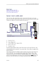
The sonar room cables include those used to connect the SC90 units to AC mains
power, as well as the control cables between the units. One high capacity Ethernet cable
connects the Transceiver Unit to the topside Processor Unit.
Context
All sonar room cables are described.
Procedure
1
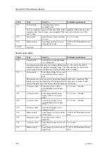
Prepare the power cables, but do not connect any units to AC mains power.
a
Connect the power cable from the uninterruptible power supply (UPS) to the
AC power outlet. (C23)
b
Connect the power cable from the Transceiver Unit to the power outlet on the
uninterruptible power supply (UPS). (C22)
c
Connect the power cable from the Power Supply Unit to the power outlet on
the uninterruptible power supply (UPS). (C24)
Standard commercial AC mains cables are used. Each cable is supplied with the
relevant unit. The typical cable length is between 1,5 and 2 meters. If this is too
short you must use an extension cable (not recommended), mount a new power
outlet within range, or make your own power cable with sufficient length.
For more information, see the cable details:
•
AC power cable using IEC C13 inline socket, page 229
2
Connect the ground cable from the Power Supply Unit to vessel ground. (C30)
This cable must be provided by the installation shipyard. For more information, see
the cable details:
•
3
Connect the ground cable from the Transceiver Unit to vessel ground.
The grounding cable for the Transceiver Unit is not listed. The grounding cable is a
special braided wire that is physically connected to the cabinet. It is connected to
vessel ground by means of the cabinet’s shock absorbers.
4
Connect the ground cable from the hull unit mounting flange to vessel ground.
A dedicated grounding cable is provided with the hull unit. One end of the cable is
already fastened to the hull unit mounting flange. The other end must be connected
to vessel ground close to the hull unit. The length of the cable is 2 metres. Use
16 mm bolts or screws.
5
Connect the power cable from the Transceiver Unit to the Power Supply Unit. (C25)
For more information, see the cable details:
•
DC power cable from Power Supply Unit to Transceiver Unit, page 246
Simrad SC90 Installation Manual
Summary of Contents for SC90
Page 2: ......
Page 16: ...14 419050 B Simrad SC90 ...
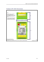
Page 219: ...419050 B 217 Øverland UPC 3005 Dimensions Cable layout and interconnections ...
Page 223: ...419050 B 221 Øverland UPC 5000P Dimensions Cable layout and interconnections ...
Page 438: ...436 419050 B 427177 Transducer dock dimensions page 494 Simrad SC90 Installation Manual ...
Page 441: ...419050 B 439 Drawing file ...
Page 442: ...440 419050 B Simrad SC90 Installation Manual ...
Page 445: ...419050 B 443 Drawing file ...
Page 452: ...450 419050 B Simrad SC90 Installation Manual ...
Page 455: ...419050 B 453 Drawing file ...
Page 458: ...456 419050 B Simrad SC90 Installation Manual ...
Page 463: ...419050 B 461 Drawing file ...
Page 468: ...466 419050 B Simrad SC90 Installation Manual ...
Page 469: ...419050 B 467 Related topics Installing the optional gate valve DN350 page 84 Drawing file ...
Page 471: ...419050 B 469 Drawing file ...
Page 473: ...419050 B 471 214043 Gate valve installation DN350 Drawing file ...
Page 475: ...419050 B 473 422915 Gate valve installation DN350 Drawing file ...
Page 477: ...419050 B 475 083045 Gate valve installation DN500 Drawing file ...
Page 479: ...419050 B 477 33414 Gate valve dimensions DN350 Drawing file ...
Page 480: ...478 419050 B Simrad SC90 Installation Manual ...
Page 481: ...419050 B 479 Related topics Installing the optional gate valve DN350 page 84 Drawing file ...
Page 482: ...480 419050 B 33473 Gate valve dimensions DN350 Simrad SC90 Installation Manual ...
Page 483: ...419050 B 481 Related topics Installing the optional gate valve DN350 page 84 Drawing file ...
Page 484: ...482 419050 B 33498 Gate valve dimensions DN500 Simrad SC90 Installation Manual ...
Page 485: ...419050 B 483 Drawing file ...
Page 487: ...419050 B 485 37357 Gate valve dimensions DN500 Drawing file ...
Page 488: ...486 419050 B Simrad SC90 Installation Manual ...
Page 489: ...419050 B 487 Related topics Installing the optional gate valve DN500 page 103 Drawing file ...
Page 491: ...419050 B 489 Drawing file ...
Page 494: ...492 419050 B Simrad SC90 Installation Manual ...
Page 495: ...419050 B 493 Related topics Installing the optional gate valve DN350 page 84 Drawing file ...
Page 497: ...419050 B 495 Drawing file ...
Page 542: ... 2018Kongsberg Maritime ISBN xxx ...
Page 543: ......
Page 544: ...Simrad SC90 Fish finding sonar Installation Manual ...

