background image

MARIS ECDIS900 Installation Manual


Page 11  


FULL MARIS SYSTEM 

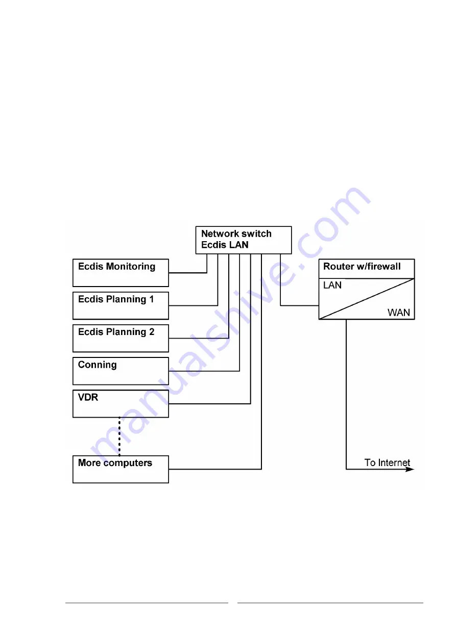
The Conning station displays in a graphical manner data that is available from the network. 
For  example,  engine,  rudder,  thruster,  etc.  This  is  typically  engine  data  from  the  VDR  and 

navigational data from the ECDIS.


The system is modular in nature, and can be extended in many ways, for example with  MARIS 

LOG4000 and/or VDR as shown below.


With the Internet connection, remote maintenance is an option when broadband is  available 

on board, which greatly reduces running service costs.


MARIS keeps a sharp eye on the modular functionality. A failing or malfunctioning 

workstation will not bring the whole system down and will not compromise safety of 
navigation.


The router is mandatory to separate the ECDIS network from the ship’s network and is 

normally part of the ship’s IT equipment. If it is missing, MARIS can supply a router.


Simply connecting to the ship’s network without a router is not allowed. 


Summary of Contents for Maris ECDIS900

Page 1: ...ENGLISH Maris ECDIS900System Installation Manual www navico commercial com ...

Page 2: ...liates reserve the right to make changes to specifications without notice GOVERNING LANGUAGE This statement any instruction manuals user guides and other information relating to the product Documentation may be translated to or has been translated from another language Translation In the event of any conflict between any Translation of the Documentation the English language version of the Document...

Page 3: ...mark of National Marine Electronics Association Maris is a trademark of Navico Holding AS Microsoft Windows 7 is a trademark of the Microsoft group of companies PLECDIS is a trademark of Simrad Egersund AS ABOUT THIS MANUAL MANUAL VERSION This manual is written for the software version in effect at the date of release for this manual The manual is continually updated to match new software releases...

Page 4: ...S 24 PREPARING THE COMPUTER FOR THE FIRSTRUN 24 FACTORY DEFAULT 24 TIME AND DATE 25 NETWORK BASICS ECDISNETWORK 25 NETWORK BASICS SENSORSNETWORK 26 NETWORK BASICS PCRADARNETWORK 26 NETWORK BINDINGS 27 SHARE FOLDERS SECURITY OPTIONS 28 TEST THE NETWORK 28 THE FINAL TOUCH 28 INSTALLING MARISAPPLICATIONS 29 ECDIS900 29 SENSOR MONITOR 29 SHIP SPECIFIC SETTINGS 31 NAVTEX 32 APPLICATION MANAGER 34 DEAD ...

Page 5: ...OUT FOR 24 42 WIRING DETAILS FOR MK15 43 HATTELAND FLAT PANEL COMPUTER MK15 43 HATTELAND MONITOR HD26T21 44 ECDIS900 PCMK5 44 INSTALLATION KITS 45 SIS4000 MK2 INSTALLATION ANDCONFIGURATION 47 C MAP CHART INSTALLATION 53 MORE ABOUT UPS 56 ECDIS CHECKLIST 59 ...

Page 6: ... the captain s quarter The maximum cable length is 15meters The split units are flexible as the monitor size can be selected from 24 to 26 inches Wide screen monitors are supported More information about the installation possibilities can be found in the chapters Electrical and Mechanical Drawings The split solution requires a standard RS232 serial cable between the units This cable carries contro...

Page 7: ...onfiguration is asfollows STANDARD DELIVERY FORMK15 The standard delivery of a single ECDISincludes USB DVD DRIVE SAMSUNG SE208 USB PANEL MNT EXTENSION CABLE 1M KEYBOARD CHERRY US ENGLISH USB MOUSE LOGITECH MARBLE USB ECDIS900 Documentation and installation kit Minimal configuration of an ECDIS MK5 is asfollows STANDARD DELIVERY FORMK5 MARIS ECDIS900 MK5 PC BRACKETS FOR MK5 PC ...

Page 8: ...Installation Manual Page 8 MARIS ECDIS900 24 Monitor KIT D SUB FOR HATTELAND MONITORS KEYBOARD CHERRY US ENGLISH USB MOUSE LOGITECH MARBLE USB SIS4000 MK2 8CH SERIAL TO LAN ECDIS900 Documentation and installation kit ...

Page 9: ...rdwired to each computer One fail does not affect the rest of the equipment that stays fully functional The ECDIS computers are networked so charts routes etc can be shared among the computers Additional sensors for example AIS and ARPA can be connected to the free ports and shared over thenetwork ECDISMK15CONFIGURATION DUAL STANDARD DELIVERY OF ECDISMK15 Two split units PC and monitor Network swi...

Page 10: ... including 8 channels NMEA interface SIS4000 MK2 Network switch TRIPLE ECDIS An extra ECDIS workstation isadded Should one fail the system falls back to a fully functional dual ECDIS which still meets the IMO requirements The ship is not forced to repair the failing ECDIS before leaving the harbor It can continue to the next convenient port ofcall ...

Page 11: ...VDR as shown below With the Internet connection remote maintenance is an option when broadband is available on board which greatly reduces running servicecosts MARIS keeps a sharp eye on the modular functionality A failing or malfunctioning workstation will not bring the whole system down and will not compromise safety of navigation The router is mandatory to separate the ECDIS network from the sh...

Page 12: ...he maximum length is 6 characters in accordance with SIS4000 MK2specifications Name Type IP Address Subnet mask Gateway DNS ECDIS network Optional 2nd IP Cx to MARIS Router Work 192 168 3 150 192 168 123 150 255 255 255 0 255 255 255 0 192 168 123 1 192 168 123 1 Sensor network Public 192 168 4 200 255 255 255 0 Not used PcRadar network Public 192 168 5 200 255 255 255 0 Not used Monitoring SIS400...

Page 13: ...o log files titled 61162 450Route log and Error61162 450 log The log files are in the folder Programdata MARIS Log ECDIS900 Error logs and error type counters are stored in C Programdata MARIS Capture Capture ini Error types ERROR2 Transmission stopped ERROR4 ACK ERROR ERROR5 QUERY RECEIVED ERROR6 Corrupted Header error ERROR7 Transmission stopped Error in header ERROR8 WRONG Destination ERROR9 No...

Page 14: ...ping QoS IEEE 802 1Q VLAN port based VLAN support and supports standards IEEE 802 3u for 100BaseT X 100BaseFX and IEEE 802 3x for flow control For more information refer to the EDS 405A Managed switch installation guide The Ethernet cables used in an ECDIS900 system are CAT5 STP four shielded twisted pairs or ISO IEC 11801 Class D DATAGRAMS The maximum datagram input rates are a 1000 for the maxim...

Page 15: ...based on an interface using a series of sentences ALF ALC ACN ARC and HBT The interface for alerts complies with the IEC 61162 1 standard ALERT LIST The alerts can be category A or category B Alert type abbreviations A Alarm C Caution W Warning Category A alerts Information Type Crossing safety contour A Crossing area with special conditions selectable C or W Crossing navigational hazards C Deviat...

Page 16: ... to the BAMS The alert titles sent to BAM may be shorter and slightly different from the alert text displayed on the ECDIS900 ALERT TITLES AND ALERT IDs SENT TO BAM Alert title Alert ID Back up navigator 99 Different geodetic datum 3005 Position system failure 3015 Failure of GYRO 3016 Master GPS changed 3017 Failure of STW 3018 Dev from pld route off trk alm 3024 End of track 3025 Early COG chang...

Page 17: ... on an uncommon baud rate Connect to Ch 7 and move the Navtex sensor to another computer with freechannels Keep the standard when installing Stick to the tables as far as it willgo SINGLE ECDIS900 Monitoring SIS4000 Mk2 GPS1 Ch1 port 8010 GPS2 Gyro Ch2 port 8011 Log Ch3 port 8012 ARPA_X Ch4 port 8013 ARPA_S Wind Ch5 port 8014 ES Ch6 port 8015 Navtex Ch7 port 8016 AIS Ch8 port 8017 Once the channel...

Page 18: ...ort 8017 Planning SIS4000 Mk2 GPS1 GPS2 Ch1 port 8020 Gyro Ch2 port 8021 Log Ch3 port 8022 ARPA_X ARPA_S Ch4 port 8023 Free Ch5 port 8024 Free Ch6 port 8025 Free Ch7 port 8026 Free Ch8 port 8027 Please note the different port numbers If the defaults are not changed the sensors will transmit on the same port leading to inaccurate data For example GPS1 and GPS2 transmitting on the same port will giv...

Page 19: ...port 8011 Log Ch3 port 8012 ARPA_X Ch4 port 8013 ARPA_S Wind Ch5 port 8014 ES Ch6 port 8015 Navtex Ch7 port 8016 AIS Ch8 port 8017 Planning SIS4000 Mk2 GPS1 GPS2 Ch1 port 8020 Gyro Ch2 port 8021 Log Ch3 port 8022 ARPA_X ARPA_S Ch4 port 8023 Free Ch5 port 8024 Free Ch6 port 8025 Free Ch7 port 8026 Free Ch8 port 8027 ...

Page 20: ...ferent port numbers If the defaults are not changed the sensors will transmit on the same port leading to inaccurate data For example GPS1 and GPS2 transmitting on the same port will give a jumping position on the ECDIS900 GENERAL When installing keep in mind that every ECDIS900 must be able to run as a standalone unit The SIS4000 Mk2 must be installed as a dedicated unit for the computer and NOT ...

Page 21: ...more See Annex Installation kits for moreinformation Note that the network cable requires special RJ45 connectors which are alsoincluded Failure to use approved items may lead the class society or the flag state to reject the installation and deny the finalapproval Do not get caught in the net use the installationkit ACPOWER MARIS standardize on 220VAC 50 60 Hz Plugs and power strips are in accord...

Page 22: ...t and take the power from the samesource as for the ECDIS900 computer BUFFERS AND EPFS Electronic Position Fixing System EPFS An EPFS can be any navigation system receiver or integrated navigation system having an IEC 61162 NMEA interface According to the Safety of Life at Sea SOLAS the navigation system must meet IMO performance standards being certified and Wheel Mark approved In practice most E...

Page 23: ... kit are screened cables Do not forget to make a proper grounding of the cables and the computers The ToughCat network cable is perfect for connecting the sensors and has 4 individually screenedpairs The RJ45 network plugs supplied will ground the cable whenfitted In addition to the mandatory sensors lay up the cables for other sensors It is common practice to connect AIS ARPA X Navtex Echo sounde...

Page 24: ...k it is also bad engineering and installation practice which can result in the loss of data and compromise safety ofnavigation PREPARING THE COMPUTER FOR THE FIRSTRUN All computers must be prepared for their particular installation installations of two ships are never alike Windows 7 US Pro 64 bit is preinstalled and configured according to MARIS specifications Start with the monitoring computer a...

Page 25: ...Time NETWORK BASICS ECDISNETWORK Change settings for TCP IPv4 as shown in thetable Other items including TCP IPv6 are not used and must be left asis Computer name Workgroup IP Address Subnet mask Gateway Monitoring MARIS 192 168 X 150 255 255 255 0 Not used Planning1 MARIS 192 168 X 151 255 255 255 0 Not used Planning2 MARIS 192 168 X 152 255 255 255 0 Not used Planning3 MARIS 192 168 X 153 255 25...

Page 26: ...ARIS VDR Set to 3 on systems connected to a MARIS VDR2200Mk2 Subnet number on new installations Set to 3 Consilium radars have 2 IP addresses per radar In this case increment the IP addresses by 5 instead of 1 to avoid conflicts NETWORK BASICS SENSORSNETWORK Change settings for TCP IPv4 as shown in thetable Other items including TCP IPv6 are not used and must be left asis Computer name Workgroup I...

Page 27: ...K BINDINGS Continue from Network and Sharing Center Change AdapterSettings On the menu line click Advanced and then AdvancedSettings d Select ECDIS network and move it to the top of the list e Select Sensor network and move it to the second line of thelist f Select PcRadar network and move it to the third line of the list Other adapters are not important but it is important that the ECDIS network ...

Page 28: ...kboxes in thelist Password protected Sharing should be OFF N A for XP Menu Control Panel Network and Internet Network and SharingCenter Advanced sharing settings TEST THE NETWORK Verify that all computers in the network can see each other shared folders and the files THE FINAL TOUCH AUTOMATICUPDATES Turn OFF Automatic Updates Open Action Center and disable thealerts ANTIVIRUSPROTECTION Turn OFF An...

Page 29: ...election here loads the correct color table for the monitor in use or loads a standard color table SCREEN DIMENSIONS Grab a ruler and measure the dimensions Enter the actual values Incorrect settings will give incorrect aspect ratio and circles on the chart will appear as ovals This is important on wide screen monitors USER PASSWORD Passwords are managed in the Application Manager See below chapte...

Page 30: ...ng the monitor the Y cable is used for connection between computer and monitor alarm panel The sensor also controls the alarm sound check that ECDIS900 alarms give an audible sound from the monitor Check that colors look right If not check the connection of the serial cable between the units and make a factory reset of themonitor Every monitor comes with its own unique color table which the Sensor...

Page 31: ...y data from the AIS SHIP PROPERTIES TABSHEET SHAPE Double click the first GPS listed Adjust the GPS antenna position until the ship is perfectly aligned alongside the quay Select the next GPS sensor and repeat the adjustment Continue until all GPS sensors have been set correctly every GPS has its own correctiontable Also set radar and conningpositions SHIP PROPERTIES TABSHEETSHAPE F DISTANCE Set P...

Page 32: ...ialog 2 The server is running Click Options Port Settings Select Network and enter the SIS4000 Mk2 Navtex sensor port to where the Navtex receiver is physically connected 3 Select Options Verify that Use NMEA Extensions is tickedon Remove all other tick marks and check that something is rollingin This depends on the receiver in use these examples are from a JRCNCR333 CRALR list of possible errors ...

Page 33: ...e turned on off in the box Readthe information by clicking the Navtex book on the acknowledge panel or by re clickingthe icon on the chart NAVTEX SLAVECONFIGURATION 1 Click Start Computer Tools Map network drive Click Browse and select the Inbox folder on the ECDIS900 computer runningthe Navtex Server Place a tick mark in Reconnect at Logon Click Finish You have now a direct access to this remote ...

Page 34: ...esktop or from the start menu C ProgramFiles MARIS AppMan AppMan Double click inside the AM grey rectangle at the top right of the screen to show theAM console b Select the administrator mode Right click in the AM console and activate the menu Enter Administrator Mode Click Ok in the password dialogue as no password has beenentered c Set up password To set up the passwords Click Security Setting t...

Page 35: ...ng the button AUTO Populate the list with the programs installed on the computer This example shows a computer running ECDIS900 PC Radar Kit and NavtexMaster Programs listed here will always run and cannot be shut down If you try to close a program or it stops it will be started againautomatically 3 Setting up Other Programs Click the button Other Populate the list with other usefulprograms The ap...

Page 36: ...lled on the computer Application Manager main window shown in Service non approved mode f Last steps Never leave the computer in Service mode It is against regulations and navigators can and will make changes to the system When configuration is complete the Operational mode must be selected to run the ECDIS900 in Approval mode To select Operational mode press the button The PC is now restarted in ...

Page 37: ...n SMonitor 1 Create if does not exist Alarm Relay Box sensor Connect the dedicated serial port to Relay Box using the proper cable here is COM1 2 In the alarm Box sensor panel populate the Output mask DEADMAN which defines the pins that are pulsed when Application Manager sends an alarm message See PLC manual BACKUP AND RESTORE REDO BACKUP Solution for Backup and Restore Images From or To Hard dri...

Page 38: ...ATION ENC and AVCS First install the permits and then install the charts from the CDsprovided Update the other computers over the network by using the function CopyDatabase ARCS First install the charts from the CDs provided and then install thepermits Update the other computers over the network by using the function CopyDatabase C Map The installation is different Please see Annex C Map chartinst...

Page 39: ...UTC time Halt on All errors Advanced BIOS features First boot device CDROM Second boot device Hard Disk Third boot device Disabled Boot other device Disabled Boot up numlock status Off Pc health status CPU warning temperature 80 C Menu Submenu New setting Standard CMOS features Date Set UTC date Time Set UTC time Halt on All errors Advanced BIOS features First boot device CDROM Second boot device ...

Page 40: ...Page 40 MARIS ECDIS900 Installation Manual ECDISMK15 MECHANICAL DRAWINGS ...

Page 41: ...Page 41 MARIS ECDIS900 Installation Manual DIMENSIONAL DRAWINGS FOR 19 TERMINAL LAYOUT FOR 19 ...

Page 42: ...Page 42 MARIS ECDIS900 Installation Manual DIMENSIONAL DRAWINGS FOR 24 TERMINAL LAYOUT FOR 24 ...

Page 43: ...Page 43 MARIS ECDIS900 Installation Manual WIRING DETAILS FOR MK15 HATTELAND FLAT PANEL COMPUTERMK15 ...

Page 44: ...Page 44 MARIS ECDIS900 Installation Manual HATTELAND MONITORHD26T21 ECDIS900 PCMK5 ...

Page 45: ...00 installation kit Key Description Part no 1 CS68 19 or CS68 24 ECDIS900 unit 2 Power cables 240 V AC and 115 V AC 3 Terminal block for 24 V DC 4 Terminal blocks for SerialInterface 5 Ferrite clamp for keyboard 000 11764 001 6 USB flash drive with charts 000 11766 001 ...

Page 46: ...4 001 13 Mounting brackets for CS68 24 000 11805 001 14 USB Extension cable 1 m 000 11802 001 15 External IEC 61162 1 2 Serial Interfaceunit 000 11803 001 11336 MBA installation kit Part no Item Qty 10626 Cable signal 4 pairs S FTP Cat5E LSFRO Toughcat cable 30 m 10185 Plug Phoenix Industrial RJ45 w screen for Toughcat cable 6 Buffers are to be orderedseparately 11236 Buffer NM 251A Part no Item Q...

Page 47: ... to 192 168 5 33 2 On the controlling ECDIS900 computer change the sensor network IP address to 192 168 5 200 3 The box has a web interface for easy programming Start Internet Explorer and go to 192 168 5 33 4 Select Set Default Values answer Yes and click Ok 5 Select Network Settings Change IP address to 192 168 4 100 Change Gateway to 192 168 4 1 Change Network mask to 255 255 255 0 Click SAVE 6...

Page 48: ...s in the box At the same time you can configure the SensorMonitor 1 Place a tick mark in channels you want enabled 2 Click the channel and the line turns blue Click the column header for the item you want to change and enter the new value Pay attention to port numbers 3 In the web interface select Channels Settings and change the name to the same as above Note The names must be identical and they ...

Page 49: ...n Manual 3 8012 8022 8032 4 8013 8023 8033 5 8014 8024 8034 6 8015 8025 8035 7 8016 8026 8036 8 8017 8027 8037 Example showing two sensors enabled Channel 8 output is alsoenabled The baud rate can be changed in menu Serial PortSettings ...

Page 50: ...ck Media Type and select Network Norm Type defaults to NMEA 0183 Sensor Click Sensor ID and give the sensor a descriptive name Click Parameters and enterthe corresponding port number in SIS4000 for both PortToRead and PortToWrite ClickOk Note Always set the same port numbers in PortToRead and PortToWrite ...

Page 51: ...AIS can be remotely controlled from the ECDIS900 where the navigators have a big screen and a decent keyboard and mouse In addition a SAR message is automatically transmitted if the Man Over Board button is clicked on the monitoring ECDIS900 To enable these functions click More Settings and place a tick mark in Send Data to The Transponder ...

Page 52: ...npredictable and useless Change the index for each sensor so they aredifferent 1 Place Sensor Monitor in Expert Mode Double right click in the right pane and select Expert Mode 2 Open the ARPA sensor and click More Settings 3 Change Target Table index from 0 to 1 4 Close the sensor 5 Double right click in the right pane and leave Expert Mode Repeat the procedure on other ARPA sensors created on co...

Page 53: ...e 2 eToken Pro 72K Java dongle Java new device 3 No Hardware Protection Software based dongle It is strictly necessary to use the correct option during installation to get eToken and license properly installed The installation is done in 2 mainsteps ECDIS900 installation including Sentinel dongle driver C Map installation eToken runtime first and then C Map SDK runtime ...

Page 54: ...CDIS900 and select eToken Pro Dongle Legacy as shownhere Continue installation by following instructions onscreen After the installation has finished check Registry for thesekeys Note The number 30516 is replaced by the actual dongle ID Check these programs have been successfullyinstalled C Map Professional SDK Runtime eToken Run Time Environment INSTALLING ETOKENJAVA Check the current version of ...

Page 55: ... Dongle Java as shownhere Continue installation by following instructions onscreen After the installation has finished check Registry for thesekeys Note The number 00002 is replaced by the actual dongle ID Check these programs have been successfullyinstalled C Map Professional SDK Runtime 5 4 eToken PKI Client 5 1 if Java eToken eToken RunTime Environment3 66 if Pro eToken ...

Page 56: ...stallation The number 3409 is an example only and it must be replaced by the actual ID number as found on the ECDIS Sentinel dongle Remove the tick mark in the box Upgrade The number is filled out automatically Set a tick mark in the box Continue installation by following instructions onscreen Check that C Map Professional SDK Runtime has been successfullyinstalled MORE ABOUT UPS The UPS is manufa...

Page 57: ...rs on a change over type on ships is doomed to go wrong because there is no noise filtering no protection of brownouts and no protection against drifting frequency Figure 1 Block diagram of a change over typeUPS The always on type The always on type has one disadvantage it isexpensive That said the rest is just what weneed A power line with fluctuating voltage or frequency and filled with noise is...

Page 58: ...n Manual Figure 2 Block diagram of an always on typeUPS Two versions of the always on type are available from MARIS DnVapproved Part number 10167 UPS Eaton EX 700 Tower 110VAC 240VAC Part number 11394 UPS Eaton EX 700 Tower 100VAC Japan ...

Page 59: ...le no C Map dongle no n a Monitor if splitinstallation n a Type Serial no Network Computer name Workgroup name MARIS IP address ECDIS network 192 168 DHCP IP address Sensor network 192 168 004 200 manual C drive unshared Folder Charts shared Folder ECDIS_UserData shared Sensor Monitor Moxa SIS SIS IP address 192 168 004 100 ...

Page 60: ... audible alarm and dimmer tested Sensor COM3 or channel1 Sensor COM4 or channel2 Sensor COM5 or channel3 Sensor COM6 or channel4 Sensor COM7 or channel5 Sensor COM8 or channel6 Sensor COM9 or channel7 Sensor COM10 or channel8 Sensor Monitor settings locked ...

Page 61: ...ty depth and route corrected ECDIS settings locked Radar Overlay n a Version no v 4 is Pci v6 is LAN 4 6 Type of radar connected S X Trigger Video HM AZI adj Main bang and skew adj Navtex n a Version no Type of Navtex receiver Serial or LAN port no Master Slave M S If Master folder Inbox shared If Slave map network drive ...

Page 62: ...MARIS ECDIS900 Installation Manual Page 62 ApplicationManager Version no Programs in Auto Other defined System locked in Approved mode Finalizing Ghost disk burned Charts installed ...

Page 63: ......

Page 64: ... 988 10960 003 www navico commercial com ...

Reviews: