Simrad ES70
5
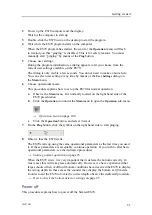
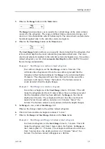
Click the
Vertical
tab. Observe that the echogram channels are shown vertically.
6
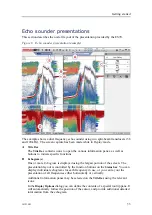
Click on one of the echograms.
Observe that the echogram then appears with a thick border line. The echogram you
have selected is now the “active” echogram. Any changes made in the
Echogram
dialog will by default only apply to this echogram.
7
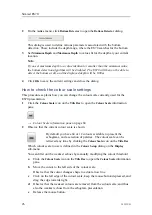
On the
Active
menu, click
Echogram
.
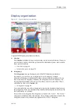
Observe that the
Echogram
dialog opens. This dialog is used to control the
appearance of the active echogram.
8
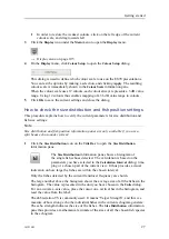
In the
Echogram
dialog, check that the
Lines
tab is shown.
The
Lines
tab in the
Echogram
dialog allows you to change the appearance of the
bottom line. You can add an extra bottom line, and in addition to this you can enable
either a white line or a hardness indicator line. The tab offers several horizontal
information lines, and you can choose the vertical scale of the echogram. Finally,
the
Lines
tab offers time or distance markers, and you can enable annotations.
9
Click
Bottom line
and
White line
to enable these. Observe the changes on the
echogram.
10
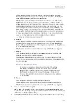
Click the
Echogram
tab.
The
Echogram
tab in the
Echogram
dialog allows you to select which TVG curve to
use for the echogram. You can choose from several standard curves, or make your
own. The tab also allows you to choose which type of echogram you wish to display.
→
on page 109
11
Change the
Echogram Type
to see the variations.
12
Click the
Horizontal Axis
tab.
13
Try the various options to see the variations on the echogram.
14
Click
OK
to save the current settings and close the dialog.
How to check the range settings
This procedure describes how to check and adjust the vertical range settings.
1
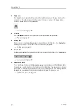
Observe the vertical range of the echograms.
Note that the vertical range is set up differently depending on the echogram type.
2
Click in a surface related echogram to make it “active”.
30
343539/B
Summary of Contents for ES70 - DOWNLOAD AND INSTALLATION REV B
Page 2: ......
Page 128: ...ISBN 13 978 82 8066 118 0 2010 Kongsberg Maritime AS ...


