Simrad ES70
System diagram
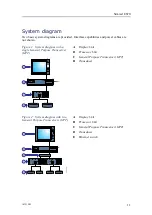
Two basic system diagrams are provided. Interface capabilities and power cables are
not shown.
Figure 1
System diagram with a
single General Purpose Transceiver
(GPT)
A
B
C
D
PWR
MENU
Transducer
+5V
+12V
-12V
HV1
HV2
TX
RX
Fuse 10A
115-230 V AC
Fuse 2A
S1
S2
12VDC
Auxiliary
Ethernet
General Purpose
Transceiver
DSP-6X
IO
POWER
Ethernet
A
Display Unit
B
Processor Unit
C
General Purpose Transceiver (GPT)
D
Transducer
Figure 2
System diagram with two
General Purpose Transceivers (GPT)
A
B
C
D
PWR
MENU
Transducer
+5V
+12V
-12V
HV1
HV2
TX
RX
Fuse 10A
115-230 V AC
Fuse 2A
S1
S2
12VDC
Auxiliary
Ethernet
General Purpose
Transceiver
DSP-6X
IO
POWER
Ethernet
Transducer
+5V
+12V
-12V
HV1
HV2
TX
RX
Fuse 10A
115-230 V AC
Fuse 2A
S1
S2
12VDC
Auxiliary
Ethernet
General Purpose
Transceiver
DSP-6X
IO
POWER
Ethernet
E
(CD024216-002)
A
Display Unit
B
Processor Unit
C
General Purpose Transceiver (GPT)
D
Transducer
E
Ethernet switch
343539/B
11
Summary of Contents for ES70 - DOWNLOAD AND INSTALLATION REV B
Page 2: ......
Page 128: ...ISBN 13 978 82 8066 118 0 2010 Kongsberg Maritime AS ...

