Simpro QUIKSTAK QS10MM User Manual Download Page 42


6.3.2


Identified Hazards 

The following hazards have been identified that are intrinsic to the Quikstak design. For each 
hazard a Risk Evaluation has been completed and control measures described. 

Blank spaces are also provided to identify, assess, and describe control measures for 
application- or site-specific hazards. 

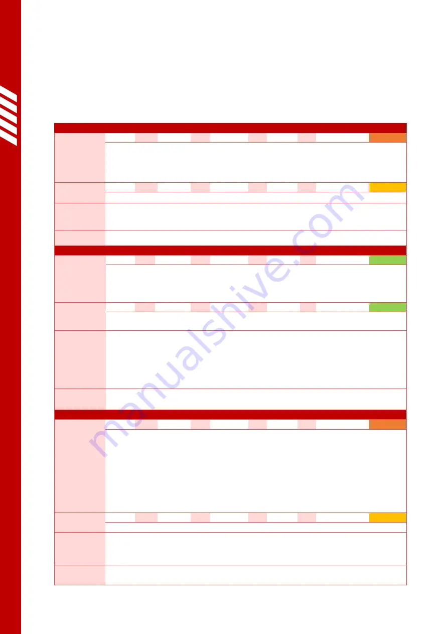
Entanglement or amputation of fingers or limbs in moving parts 

Operator 

LO: 

FE: 

DPH: 

NP: 

Risk Factor: 

16 

The Quikstak is designed so that potential trapping points and shear hazards are 
eliminated, minimized, or isolated by guarding. 
When QUIKSTAK MODE is enabled, the forks will not descend below 200mm 
without manual control input. 

Other  
persons 

LO: 

FE: 

2.5  DPH: 

NP: 

Risk Factor: 

10 

Other persons will less frequently be in proximity to moving parts. 

Control 
measures 

Operators are responsible to obey warning signs fitted to the machine and 
instructions regarding keeping clear of all moving parts. 

Comments   

Being struck by objects falling off the forks 

Operator 

LO: 

FE: 

DPH: 

NP: 

Risk Factor: 

When being used as pallet stacker, the Operator is shielded from the load by 
the body and mast of the stacker. 
When using QUIKSTAK MODE it is possible for product to fall off the pallet and 
strike the operator. 

Other  
persons 

LO: 

FE: 

DPH: 

NP: 

Risk Factor: 

When being used as a pallet stacker, it is possible for product to fall off the 
pallet and strike persons standing near the stacker. 

Control 
measures 

Product must be stacked carefully, and the load should be lifted no more than 
500mm when being transported. 
Ramps should always be traversed in a direction which causes the load to 
recline against the fork carriage. 
Operators are responsible to keep themselves and others well clear of the forks 
when lifting loads higher than 1000mm. 

Comments 

Low-speed mode is automatically engaged when the forks are raised above 
500mm. 

Crushing due to rapid and/or uncontrolled descent of the forks 

Operator 

LO: 

0.5 

FE: 

DPH: 

NP: 

Risk Factor: 

16 

There is no physical guarding preventing personnel from accessing the area 
beneath the forks. 
A pressure-compensating valve limits the lowering speed of the forks in normal 
operation, and a hose-burst valve prevents the forks from falling in the event of 
a hydraulic failure. 
When QUIKSTAK MODE is enabled, the forks will not descend below 200mm 
without manual control input. 
Significant safety margins ensure that the probability of failure of any steel, 
hydraulic, or control parts failing is very low. 

Other  
persons 

LO: 

0.5 

FE: 

2.5  DPH: 

NP: 

Risk Factor: 

10 

Other persons will less frequently be in proximity to the forks. 

Control 
measures 

Operators are responsible to obey instructions and warnings regarding keeping 
themselves and others away from the area beneath the forks at all times. 
The Quikstak must be regularly maintained, and all faults promptly repaired. 

Comments   

Summary of Contents for QUIKSTAK QS10MM

Page 1: ...User Manual Quikstak QS10MM Original Instructions English v52 0 April 2022 USER MANUAL...

Page 2: ...ce and international conformity this document uses Syst me International SI units These may be converted to Imperial units as follows 1 kilogram kg 2 2 pounds lb 1 metre m 1000 millimetres mm 39 37 in...

Page 3: ...User Manual Quikstak QS10MM Original Instructions English v52 0 April 2022 Page 2...

Page 4: ...11 2 3 2 Steering 12 2 3 3 Braking 12 2 3 4 Towing 12 2 4 Handling pallets 12 2 5 Using the Quikstak height levelling system 13 2 5 1 Stacking goods 13 2 5 2 De stacking goods 14 2 6 Parking the stack...

Page 5: ...System 30 4 7 1 Control panel 30 4 7 2 PLC 30 4 7 3 Laser sensor 30 4 7 4 LED strobe light 30 4 8 Preventative Maintenance Inspections 31 4 8 1 Pre inspection checklist 31 4 8 2 Inspection checklist...

Page 6: ...Equipment every QS10MM is self propelled as standard with a unique monomast design providing an unrestricted field of view The QS10MM height levelling feature is based on laser technology When turned...

Page 7: ...hain guarding control tiller with controls one steered drive wheel and one balance castor a drive motor and gearbox a hydraulic powerpack batteries electronic control systems and a powerpack cover 1 3...

Page 8: ...al service life of the Quikstak is as follows Average Gross Pallet Weight Intended operational life 200kg 100 000 lift lower cycles 200kg 800kg 75 000 lift lower cycles 800kg 1000kg 50 000 lift lower...

Page 9: ...This manual is written in English and is to be considered the Original Instructions for the purposes of EU Machinery Directive 2006 42 EC 3 Operator s must read and understand this manual before using...

Page 10: ...Risk Assessment should be completed as per 6 3 Never attempt to operate the Quikstak if it is damaged or malfunctioning 2 1 Identification of controls 2 1 1 Tiller controls Ref Name Function LOWER BU...

Page 11: ...ikstak controls Ref Name Function EMERGENCY STOP Instantly shuts off the power and disables the stacker USER MANUAL QR CODE QR code linking to an online PDF User Manual TEACH HEIGHT BUTTON Records a n...

Page 12: ...kstak 2 3 1 Driving The control tiller is used to control the travel direction and speed of the Quikstak To drive the stacker the tiller must be positioned within the zone marked READY in the diagram...

Page 13: ...ake Regenerative braking will not be used If the tiller handle is released by the operator it will pivot to the upper BRAKE zone automatically 2 3 3 3 Regenerative braking Moving the DRIVE LEVER to th...

Page 14: ...8 Once the pallet is deposited briefly press the RAISE button to lift the forks 10mm 9 Slowly reverse the Quikstak in a straight line until he forks are completely disengaged from the pallet The Quik...

Page 15: ...the QUIKSTAK MODE button 2 1 3 again to deactivate the height levelling system The full pallet can now be transported and stored and another empty pallet collected as per Step 1 2 5 2 De stacking good...

Page 16: ...MERGENCY STOP button 5 If necessary place the stacker on charge as per 2 7 These procedures should be carried out even if the Quikstak is only unused for a short period of time Never park the Quikstak...

Page 17: ...oes and suitable protective clothing Do not wear loose clothing as it may be caught resulting in dangerous entrapment Long hair should be tied back Operator should carefully familiarise themselves wit...

Page 18: ...round when the stacker is not in use The operator must always have a view of the direction of travel If the view forward is obstructed by the load drive the stacker backwards or request the guidance o...

Page 19: ...vy loads for prolonged periods of time Load safety Park the stacker in a designated marked parking space Never park on sloping ground or in a position where it will obstruct other traffic Lower the fo...

Page 20: ...1 2 Key switch 1030381514 EMERGENCY STOP button depressed Pull the EMERGENCY STOP outwards to enable the power 2 1 3 E Stop 1030381516 Flat batteries Check battery indicator and recharge batteries if...

Page 21: ...ition sources 4 4 Electrical System The Quikstak is fitted with an onboard charger and two 12V 85Ah AGM deep cycle batteries connected in series to provide 24VDC to the control circuits and motors A C...

Page 22: ...otective Equipment must be worn If battery acid comes into contact with the skin or eyes the affected area should be immediately rinsed with fresh water for ten minutes and medical assistance requeste...

Page 23: ...it 4 4 5 Charging lead The Quikstak is fitted with an extendable 2 metre charging lead which is stowed in the fascia as per Figure 11 By default this lead has an IEC Type I plug suitable for use in Au...

Page 24: ...netic brake jammed on High temperature operating environment 12 THROTTLE FAULT Throttle Pot Wiper out of range Throttle Pot wiring broken or shorted Throttle Pot broken or defective Wrong throttle typ...

Page 25: ...e fault Improper sequence of throttle KSI push or inhibit inputs Throttle Pot misadjusted 41 CURRENT SENSE FAULT Current sensor out of range Short circuit in drive motor or wiring Controller failure 4...

Page 26: ...4 4 9 Wiring diagram C O N TR O L L ER C U R TIS1212...

Page 27: ...lacing the hydraulic fluid Do not mix hydraulic fluids of different grades Do not add used or impure hydraulic fluid Do not fill the reservoir beyond the maximum fill marking 5 litres Always store and...

Page 28: ...lower right to the ground 4 5 6 1 Adjusting the chain length Observe the following procedure to adjust the roller chain 1 Park the Quikstak with no load as per 2 6 taking particular care to lower the...

Page 29: ...ing rail The forks can also be removed altogether to minimise volume for shipping 4 6 Drive Mechanical Systems 4 6 1 Drive motor The Quikstak is fitted with an 0 65kW DC electric motor delivering powe...

Page 30: ...ocedure to adjust the Quikstak straddle width 1 Remove the weight of the stacker from the outriggers by either a Placing a hydraulic jack beneath the front centre of the stacker frame and jacking it u...

Page 31: ...r altering program parameters PLC programming software is available from Simpro Authorisation must be obtained from Simpro before any changes are made to the PLC programming 4 7 3 Laser sensor The hei...

Page 32: ...2 Ensure there are no ignition sources within two metres of the stacker 3 Remove the pallet or load and lower the forks to the ground 4 Turn off the key switch and unplug the charging lead 5 Remove th...

Page 33: ...and or adjust if necessary 17 Tiller handle Check that tiller quickly returns to vertical when released 18 Wheels Inspect wheels for wear and damage 19 Bearings Check wheel bearings lubricate or repl...

Page 34: ...4 8 3 Inspection log sheets Date Name Location Checks complete Maintenance carried out Parts used...

Page 35: ...User Manual Quikstak QS10MM Original Instructions English v52 0 April 2022 Page 34 Date Name Location Checks complete Maintenance carried out Parts used...

Page 36: ...Date Name Location Checks complete Maintenance carried out Parts used...

Page 37: ...User Manual Quikstak QS10MM Original Instructions English v52 0 April 2022 Page 36 Date Name Location Checks complete Maintenance carried out Parts used...

Page 38: ...orks turn the Quikstak off and depress the EMERGENCY STOP 2 Check that the lifting equipment is in good condition and rated to least 1000kg 3 Attach a sling or chain to the lifting equipment and faste...

Page 39: ...position using strops rated to at least 1000kg and marked tie down points Ensure it is secured against lateral forces from any direction If the transport vehicle is uncovered it is recommended to tra...

Page 40: ...en QUIKSTAK MODE is engaged providing a visual cue that the forks are under automatic control 9 A PLC control program which prevents the forks from descending below 200mm when QUIKSTAK MODE is engaged...

Page 41: ...x NP RISK FACTOR 6 3 1 2 Risk Evaluation Once the Risk Factor is determined the risk can be evaluated using the following table Risks evaluated as Very High Extreme or Unacceptable are likely to requ...

Page 42: ...it is possible for product to fall off the pallet and strike persons standing near the stacker Control measures Product must be stacked carefully and the load should be lifted no more than 500mm when...

Page 43: ...and maintenance work should only be carried out by authorised qualified technicians Comments All extension leads and power cables should be tested and tagged by a registered electrician at regular int...

Page 44: ...jamming open due to control system failure Operator LO 0 5 FE 4 DPH 1 NP 1 Risk Factor 2 If the lowering valve is jammed open due to a control circuit failure the forks will descend to the ground at...

Page 45: ...ing equipment some residual hazards may be present despite any interlocks guarding or other safety systems that may be implemented The machinery owner has a legal responsibility to take all reasonable...

Page 46: ...AGM case 256mm long x 165mm wide x 210mm high 2 1030381519 Charger 24V 10A with looms and plugs ESCH24V10A 1 1030381534 Charging Lead extendable with IEC Type I plug 1 1030381544 Fuse 150A for electr...

Page 47: ...ttons LED and ribbon cable 1 0210050006 PLC 12 24VDC with 8x digital analog inputs 8x relay outputs APB 12MRDL 1 0790050462 Laser Sensor Sick DT35 1 0790050463 Laser Sensor Cable 2m long with female p...

Page 48: ...h14 mm 860 1200 860 1200 4 1 Height outriggers h8 mm 100 100 4 15 Lowered height h13 mm 60 60 4 19 Overall length l1 mm 1570 1570 4 2 Length to face of forks l2 mm 500 500 4 21 Overall width b1 b2 mm...

Page 49: ...User Manual Quikstak QS10MM Original Instructions English v52 0 April 2022 Page 48 Rated Capacity kg Load Centre Chart 200 400 600 800 1000 300 600 900 1200...

Page 50: ...ng their product with Simpro This may be done using the web form here https simpro world support warranty registration 15 Application for Warranty Consideration Form means the system used to file a Wa...

Page 51: ...before going to see the machine 2 The Service Agent should contact Simpro for assistance in identifying the fault if it is not apparent This step is important so that if a site visit is necessary the...

Page 52: ...gement Simpro s OEM products are now sold around the world through a distribution network covering most large economies The product range continues to evolve thanks to a policy of continuous R D new i...

Reviews: