SimpliVity OmniCube CN-2000 Installation And Maintenance Manual Download Page 58

CN-Series Hardware Installation and Maintenance Guide

Direct-Connected Storage Network Configuration

• Separate the SimpliVity Storage, Management, and Federation networks by using VLANs on each

switch.

Related Topics

Obtaining Hardware That is Not Supplied

on page 20

Direct-Connected Storage Network Configuration

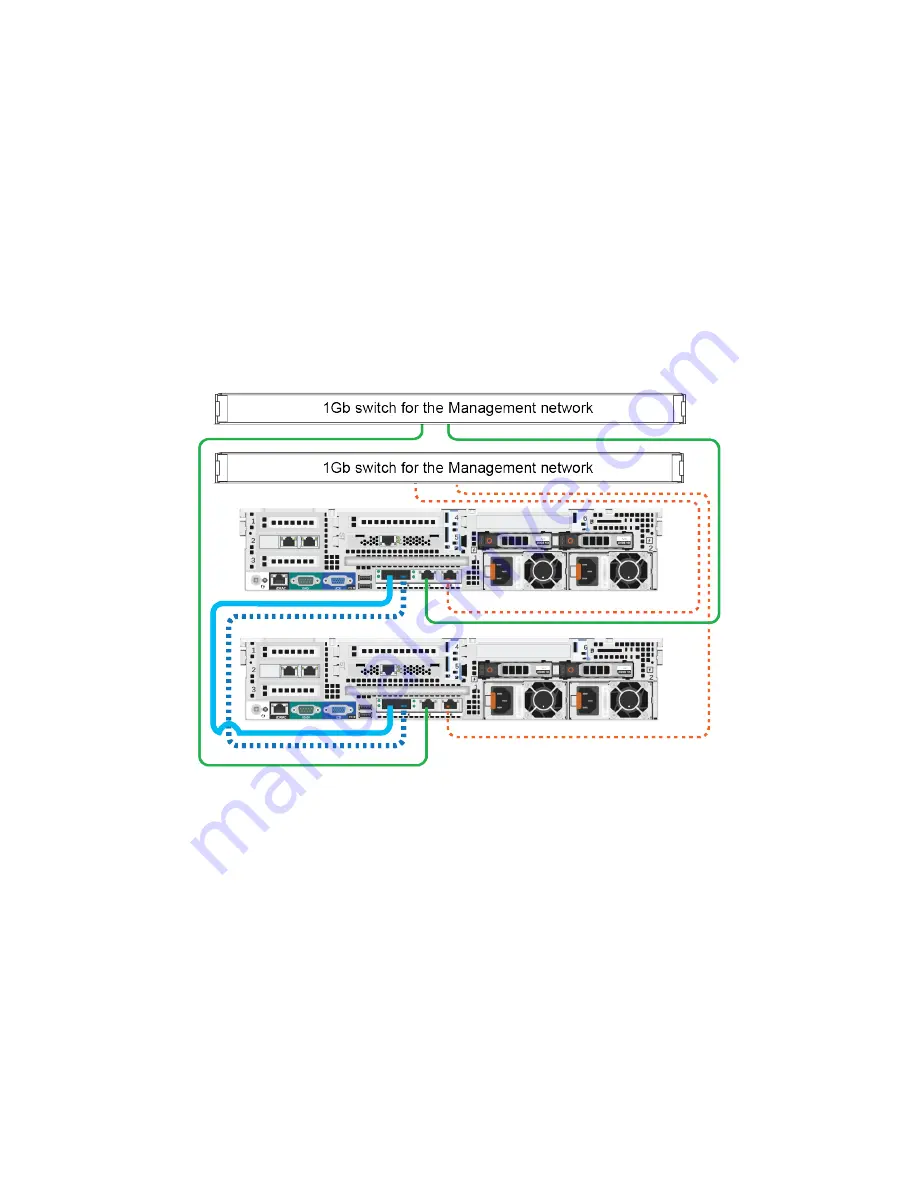
The following image shows a minimum two-OmniCube network configuration that uses redundant, direct
10GbE connections for the Storage and Federation networks and redundant 1GbE connections to 1GbE
switches for the Management network.

Notes:

This network configuration requires additional cables not supplied in the shipping carton.

Guidelines for this network configuration:

• You cannot use direct connections for the Storage network if you have three or more systems in a

Federation datacenter.

• Use two SFP+ Direct Attach cables (or Fiber Optic cables) to directly connect the 10GbE network

interfaces on each system.

• For each system, you use two network cables to connect the 1GbE network interfaces to different

1GbE switches.

• Port 1 on system A must connect to port 1 on system B and port 2 on system A must connect to port 2

on system B.

Related Topics

Obtaining Hardware That is Not Supplied

on page 20

58

Summary of Contents for OmniCube CN-2000

Page 1: ...OmniCube CN Series Hardware Installation and Maintenance Guide CN 2000 CN 2200 CN 3000 CN 5000...

Page 2: ...demarks of SimpliVity Corporation in the United States and certain other countries All other trademarks are the property of their respective owners Information in this document is subject to change wi...

Page 3: ...mponents 19 Obtaining Hardware That is Not Supplied 20 Rack Requirements 20 Switch Recommendations 21 Understanding the Networks Used in a Federation 22 Task 2 Installing Each CN Series System in a Ra...

Page 4: ...Monitoring 45 Viewing Network Interface Status in the vSphere Client 46 Ports Required for Network Communication 46 5 Drive Maintenance 49 Guidelines for Maintaining Drives 49 Removing a Drive 50 Inst...

Page 5: ...irtual machines VMs in the Federation As your capacity and performance needs increase you can add more OmniCube systems for easy on demand scalability with no disruption to users This guide applies to...

Page 6: ...ify support about significant events Ensure you have the CN Series system serial number which is recorded on the Service Tag a pull out card located CN 2000 CN 2200 and CN 3000 Under drive 2 on the fr...

Page 7: ...need more capacity or performance you can add more OmniCube systems to the Federation with no disruption to users The following table describes the components of the 2U CN Series system models Compone...

Page 8: ...ore 2 x 750W 16 core or 2 x 1100W 24 core 2 x 1100W Network Interfaces Embedded 2 x 10GbE and 2 x 1GbE VM Network optional N A 2 x 10GbE or 2 x 1GbE1 Deduplication and Compression OmniCube Accelerator...

Page 9: ...rading system software 6 Video input Enables you to connect a monitor as part of a KVM for local administration 7 Storage 3 5 disk drives with power top and activity bottom LED indicators Labels indic...

Page 10: ...5 USB connector USB 2 0 compliant connector Enables you to connect a USB device such as a keyboard as part of a KVM for local administration 6 Video Input Enables you to connect a monitor as part of a...

Page 11: ...nsert a flash drive for software upgrades 8 Two 10GbE network interfaces numbered 1 and 2 Each 10GbE interface has link top and activity bottom round LEDs These interfaces are dedicated to SimpliVity...

Page 12: ...auto ranging Make sure each power source has sufficient electrical overload protection Frequency 50 60Hz 50 60Hz Heat dissipation BTU hr max 2843 2891 BTU hr max 4100 BTU hr max Maximum inrush current...

Page 13: ...tem models Specification Maximum System Limit Altitude operating 15 2m to 3048m 50 ft to 10 000 ft Altitude storage 15 2m to 12 000m 50 ft to 39 370 ft Contaminant level operating Class G1 or lower as...

Page 14: ...14...

Page 15: ...m the bottom of the rack Always install a CN Series systemin a horizontal position or you void your warranty and support contract Related Topics Rack Requirements on page 20 Task 2 Installing Each CN...

Page 16: ...w to protect sensitive hardware Unpack the shipping box and make sure the shipping box contents are complete Gather the hardware needed for the installation but not provided in the shipping box Learn...

Page 17: ...iderable tension Cut these with an appropriate tool and use appropriate safety wear The following image shows the carton contents for a 2U model To unpack the shipping carton 1 Remove the shrink wrap...

Page 18: ...acity Bezel Protects disk drives in the CN Series system front panel Two power cords 15amp NEMA 5 15P to C13 power cord Connects a CN Series system to power 15amp C14 to C13 power cord Connects a CN S...

Page 19: ...t Component 1 Front rail bracket secures the rail to a rack column using holes at position 1 and 4 in the 2U space 2 Rear rail bracket secures the rail to a rack column using holes at position 3 and 6...

Page 20: ...a 10GbE network interface on a CN Series system to a 10GbE network interface on another CN Series system or to a switch The number and type of cables you need depends on your network configuration and...

Page 21: ...zed or bayed according to the manufacturer s instructions When servicing an enclosure in a rack extend only one enclosure at a time to prevent the rack from tipping The tooled rail mounting configurat...

Page 22: ...you can connect the 10GbE network interfaces to a switch Federation network 10GbE network used for communication between Virtual Controllers within a Federation datacenter and does not route to remote...

Page 23: ...the rail kit box contain important safety and procedural information To install the rail kit 1 Pull apart the front and rear rail brackets lengthening the rails to the correct distance for your rack 2...

Page 24: ...old the enclosure over the rails aligning the lugs with the J slots 4 Starting at the back two lugs gently rotate the enclosure down in the direction of arrow C engaging the lugs in the J slots Note T...

Page 25: ...supply UPS systems to protect against a complete power outage The following image shows the recommended rack power cable connections for a basic two OmniCube Federation Use a similar cabling configur...

Page 26: ...s shown in the following image Other networking interfaces are Each CN Series system has a separate 1GbE IPMI network interface that you can use for the initial system setup and remote management The...

Page 27: ...t kit After organizing the cables you can attach the bezel Related Topics Attaching and Removing the Bezel on page 31 Task 5 Configuring IPMI for Remote Management Before deploying an OmniCube to a Fe...

Page 28: ...the laptop from wireless networks To configure IPMI 1 Connect an Ethernet cable from the laptop s Ethernet port to the IPMI Ethernet port on the rear of the OmniCube 2 If necessary change the IPv4 add...

Page 29: ...If you are not using VLANs this must be unchecked 10 Click Apply then Logout to exit IPMI 11 Remove the Ethernet cable from the IPMI port in the OmniCube and replace it with a cable that is connected...

Page 30: ...o connect to IPMI and launch the Virtual Console 1 Log in to any computer in the same network as your IPMI 2 Type the IPMI IP address into your browser For example http 110 150 0 12 3 Use the default...

Page 31: ...cal security for the drives in the front panel To attach the bezel 1 Identify the front panel mounting lugs on the right side of the system 2 Insert the bezel tabs into the front panel mounting lugs 3...

Page 32: ...tallation and Maintenance Guide Attaching and Removing the Bezel 2 Rotate the left side of the bezel outward from the front panel and pull to the left to simultaneously disengage the tabs on the right...

Page 33: ...3 Connecting to IPMI and Launching the Virtual Console on page 30 Accessing VMware ESXi Through the IPMI Virtual Console You use the Virtual Console to access the instance of VMware ESXi installed on...

Page 34: ...for Remote Management on page 27 Connecting to IPMI and Launching the Virtual Console on page 30 Accessing VMware ESXi Through the IPMI Virtual Console on page 33 Configuring the Management Network A...

Page 35: ...5 Configuring IPMI for Remote Management on page 27 Connecting to IPMI and Launching the Virtual Console on page 30 Accessing VMware ESXi Through the IPMI Virtual Console on page 33 Configuring a VLAN...

Page 36: ...nd Launching the Virtual Console on page 30 Accessing VMware ESXi Through the IPMI Virtual Console on page 33 Configuring the Management Network IP Settings Before You Begin You have configured IPMI a...

Page 37: ...efore You Begin You have configured IPMI and launched the Virtual Console You have logged in to VMware ESXi To configure the DNS settings 1 Select DNS Configuration in the Configure Management Network...

Page 38: ...o the Configure Management Network screen 4 Press Esc Escape to return to the ESXi System Customization screen 5 Press Y yes to confirm the management network changes 6 Select Test Management Network...

Page 39: ...r occurs The indicators can help you correct problems before they affect service levels The following image shows the diagnostic indicators on the front panel and the colors they glow depending on the...

Page 40: ...e LEDs on the front of each drive indicate when there is a problem such as a failed or failing drive You can also view drive status in your vSphere Client If a drive fails or is failing contact your s...

Page 41: ...Write I O activity is occurring If a drive fails or is failing contact your support provider to obtain a replacement drive of the same type size and speed Related Topics Front Panel Description on pa...

Page 42: ...pply has an illuminated translucent handle that indicates whether power is present or whether a power fault has occurred Not lit Indicates no power present Steady green Indicates the power supply is c...

Page 43: ...yellow LED 2 bottom glows or flashes green or red The following table lists the LED states System State LED 1 LED 2 Status Description Power up Off Off PCIe 12V power is not present Power up Off Stea...

Page 44: ...ccelerator card to ensure that the card is operational To view Accelerator card status 1 In your vSphere Client expand the datacenter that contains the CN Series system 2 Select the CN Series system 3...

Page 45: ...that the capacitors on the Accelerator card have fully discharged 4 Power on the OmniCube 5 Wait for the OmniCube to fully boot and reconnect to your vSphere Client 6 Verify that both LEDs on the Acce...

Page 46: ...tem to ensure that the interfaces are operational To view network interface status 1 In your vSphere Client expand the datacenter that contains the CN Series system 2 Select the CN Series system 3 Sel...

Page 47: ...intenance Guide Network Interface Monitoring Port Network Interface Description 111 with Port Mapper enabled Storage eth2 Storage traffic between OmniCube systems and when existing ESX hosts are confi...

Page 48: ...48...

Page 49: ...drive Protect drives from electrostatic discharge Wear an electrostatic wrist strap when handling a drive unless it is protected from electrostatic discharge Handle drives carefully Hold a drive only...

Page 50: ...ity You have read the guidelines for maintaining disk drives You have read the guidelines for protecting hardware from electrostatic discharge To remove a drive 1 Remove the bezel if necessary 2 Exami...

Page 51: ...hardware from electrostatic discharge Verified that all backup operations are up to date Drive replacement requires a RAID rebuild which might take some time to complete on a system that contains many...

Page 52: ...the drive into the slot stopping when you feel resistance 6 Simultaneously rotate the handle upward and press the drive completely into the slot 7 Examine the LEDs and event messages to ensure the di...

Page 53: ...supply until you are ready to replace it A CN Series system can operate with only one functioning power supply However replace a failed or failing power supply as soon as possible Replace a power sup...

Page 54: ...e latch to the right 4 Gently pull the power supply from the slot Related Topics Protecting Sensitive Hardware from ESD on page 16 Guidelines for Maintaining Power Supplies on page 53 Power Supply Mon...

Page 55: ...ure that the power supply is fully inserted and locked in by the orange spring loaded clip 5 Connect and secure the power cable to the new power supply 6 Ensure that the power cables are fully inserte...

Page 56: ...56...

Page 57: ...The following image shows the minimum network configuration for a two OmniCube Federation that uses redundant 10GbE connections to two 10GbE switches and uses VLANs to separate the SimpliVity Storage...

Page 58: ...E switches for the Management network Notes This network configuration requires additional cables not supplied in the shipping carton Guidelines for this network configuration You cannot use direct co...

Page 59: ...edundant connections to 1GbE switches for the Management network Note This network configuration requires additional cables not supplied in the shipping carton Guidelines for this network configuratio...

Page 60: ...60...

Page 61: ...zing 27 power 16 25 rail kit management 19 SFP 18 58 59 strain relief 25 straps 19 capacity 5 7 carton 17 contents 17 circuit redundancy 25 CISPR compliance 13 CMA 18 organizing cables 27 straps 27 CN...

Page 62: ...an 8 power supply 11 fastener power cable 25 FCC compliance 13 Federation 5 dedicated network interfaces 11 network 22 59 flash drive 11 18 documentation 18 software 18 front panel 8 9 service tab 27...

Page 63: ...nt 22 K KVM 9 11 L latches 9 LED 11 extension cable 18 limits configuration 7 humidity 12 shock and vibration 12 temperature 12 M maintaining disk drives 49 power supplies 53 system 39 management netw...

Page 64: ...placement 53 rack distribution 21 specifications 12 voltage 12 power supply replacing 53 slot 53 Product Information Guide 23 PSU 11 53 R rack 5 EIA 310 E compliant 21 EIA 310 E rack 21 hardware 20 la...

Page 65: ...thermal indicator 39 specifications 12 troubleshooting Accelerator 43 cooling 39 diagnostic indicators 39 drives 39 40 49 electrical 39 events and alarms 39 health status 39 LED 11 memory 39 PCI 40 p...

Page 66: ......

Reviews: