9-3
4007ES Panel Programmer Manual (
579-1167)
Custom Control,
Continued
Anatomy of a
Custom Control
Equation
Using Logical Operators (AND, OR, NOT) you can link multiple input statements to form
logical expressions. Logical operators are only used with input statements and are not used
with Output statements. ES Panel Custom Control uses the following logical operators.
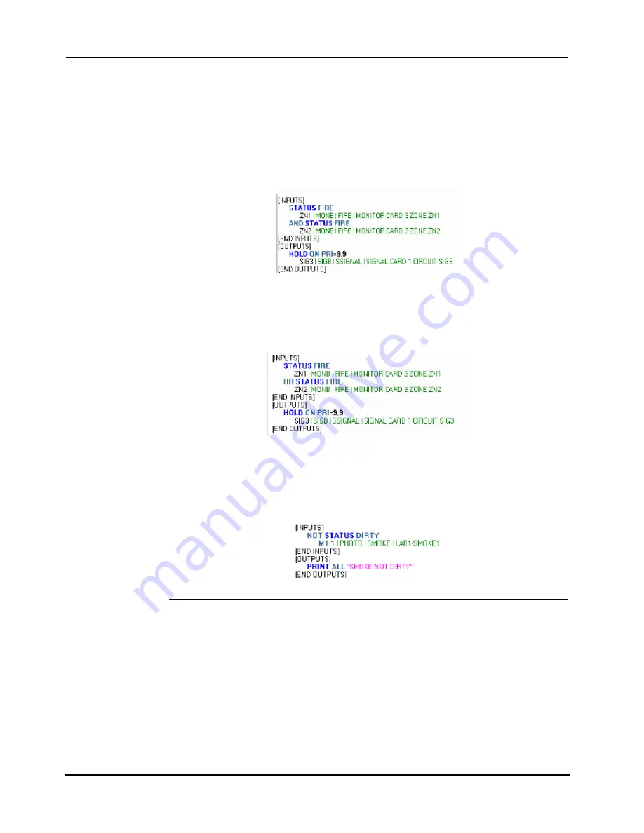
• AND Operator. With the AND logical operator you can put a group of points in series
so that only the activation of all points at the same time causes the Output side of the
equation to occur. In the following example, Zone1 and Zone2 must both be in alarm
(FIRE) before the output (Hold ON SIG3) executes.
Figure 9-3. Logical Operator: AND
• OR Operator. With the OR operator you can put a group of points in parallel, meaning
the activation of any one of the points causes the output side of the equation to execute.
In the following example, if either Zone1 or Zone2 enters an alarm state, the output
(Hold ON SIG3) executes.
Figure 9-4. Logical Operator: OR
• NOT Operator. Use the NOT Operator to specify that a condition must not be true in
order for the output to execute. In the following example, the output side of the
equation (print message “Smoke not dirty” executes only if the condition of M1-1 is
NOT dirty.
Figure 9-5. Logical Operator: NOT
Using a Ladder
Logic Diagram to
Evaluate an
Equation
A ladder logic diagram is a “sketch” of the equation used to evaluate (predict the outcome) of a
custom control equation before it is entered into the programmer. Use the following
conventions when creating ladder logic diagrams:
• Draw a solid, vertical line on the left side of the sketch to represent the starting point
for the equation. Use a vertical dashed line to divide the sketch into an input side and
an output side.
• Use two vertical, parallel lines to represent each input statement. Add text between the
lines to describe the input statement.
Continued on next page
Summary of Contents for 4007ES Panels
Page 1: ...4007ES and 4007ES Hybrid Fire Alarm Systems Programmer s Manual 579 1167 Rev D...
Page 2: ......
Page 4: ......
Page 10: ......
Page 18: ......
Page 36: ......
Page 56: ......
Page 122: ...9 38...
Page 132: ......
Page 134: ......
Page 150: ......
Page 166: ...A 16...
Page 167: ......


