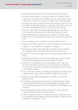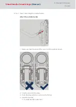
28.Check that the outer handle can turn easily; if it does not, there may be
a problem with the mortise lock (9) or the handle may have been fitted
incorrectly. In case of doubt, disassemble components and start again
from Step 4.
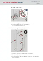
29.Push inlay (17) onto the inside handle (15). Depending on the handle
model, it may not be possible to fit it once the handle is installed.
30.Push inside handle (15) onto the inner fitting (12) fastening flange until it
will go no further.
31. Tighten the inside handle (16) hexagon screw firmly by hand, using
about 5-7 Nm.
32. Push the cover (17) over the inside handle (15).
33. Carefully push the inlay (18) through the opening in the inside cover (17).
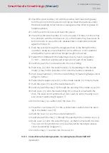
34.Push the cover (17) onto the inside fitting (12), so that it is flush with the
door. The cover is not symmetrical; look carefully at the marking to en-
sure correct positioning.
35.Click the inlay (18) carefully into the cover (17).
36.Push the cover (2) over the outside handle (3). The cover is used as an
antenna for the LockNode.
37. Carefully push the inlay (1) through the opening in the outside cover (2).
38.Push the cover (2) onto the outer fitting (4), so that it is flush with the
door. The cover is not symmetrical; look carefully at the marking to en-
sure correct positioning.
39.Click the inlay (1) carefully into the cover (2).
8.9.6 Conventional fastening system for Scandinavian Oval MO
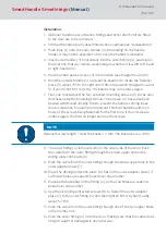
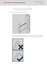
If an additional mechanical cylinder is to be installed to double-lock the
door, you must ensure that the cable from the outer fitting cannot be
pulled through the lock. There are two options to choose from:
Pull cable through the door via the lock. In doing so, you must ensure
that the cable does not get damaged in any way. You will need to
remove the mortise lock from the door or at least loosen the fastening
screws.
Enlarge the upper hole, so that the cable can be easily pulled through
the door via the lock. The hole diameter should be no larger than 45
mm; otherwise, there is a risk that the fitting will no longer cover the
hole. In principle, it is also possible to enlarge the hole upwards only to
form an elongated hole.
SmartHandle
SmartIntego
(Manual)
8. Installation (manual)
106 / 160
Summary of Contents for SI:SmartHandle Series
Page 1: ...SmartHandle SmartIntego Manual 28 10 2020...
Page 25: ...6 5 Distances and door thicknesses SmartHandle SmartIntego Manual 6 Designs 25 160...
Page 131: ...SmartHandle SmartIntego Manual 8 Installation manual 131 160...
Page 132: ...9 Outer fitting is mounted SmartHandle SmartIntego Manual 8 Installation manual 132 160...
Page 136: ...2 Remove the uppermost battery SmartHandle SmartIntego Manual 8 Installation manual 136 160...
Page 137: ...3 Screw on the inside fitting SmartHandle SmartIntego Manual 8 Installation manual 137 160...
Page 145: ...10 Configuration See TechGuide WO SVCN SmartHandle SmartIntego Manual 10 Configuration 145 160...
Page 147: ...12 Signal See TechGuide WO SVCN SmartHandle SmartIntego Manual 12 Signal 147 160...

