


(iv). When the SDB680 is installed into a rack, support shelves should be used. These
are available from Simoco and supplied as a pair with all the necessary screws for
securing them.
CAUTION
EQUIPMENT DAMAGE. When the SDB680 Base Station is installed into a
rack, DO NOT use the front panel attachment points to support the full
weight of the equipment or damage to the equipment may result.
Suitable shelves or supports MUST be provided to support the body of
the base station along the length of each side.
5.3. FITTING THE SDB680 BASE STATION
To fit the SDB680 into a rack on to support brackets, carry out the following:
1. Hook the support shelve brackets onto either side (internal) of the rack at equal
heights.
2. Fit the M6 cage nuts into the appropriate positions on the front rack mounting
support rails.
3. At the front of the rack, position the rear of the base station onto the support
brackets and slide the base station into the rack, checking that it does not
catch on anything.
4. Secure the base station into the rack using the four M6 x 12 mm pozidriv
retaining bolts with plastic cup washers (two per side).
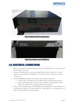
5.4. ELECTRICAL CONNECTIONS
1. Refer to the Electrical Connections section, for full details of all connections and
the connector pin-outs.
2. Using a suitable test set, e.g. an Anritsu/Wiltron S331A, check the Tx and Rx
antenna connections for a VSWR of 1.5:1 or better at the relevant Tx and Rx
Frequencies.
3. On the SDB680 rear panel, carry out the following:
a. Connect the Tx and Rx antenna cables to their respective N-type
connectors.
b. Ensuring that the power source is switched off, connect the DC power
cable from the ‘DC IN’ connector to the power source.
4. Carry out the configuration of the SDB680 in accordance with Todo//Section 3 –
Configuration of New Tier II Base Station or Todo//Section 4 – Configuration of
New Tier III Base Station as appropriate.
Doc Number:
TNM-I-E-0046 ISSUE 1.2
Page
38


