


53
EN
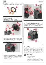
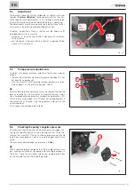
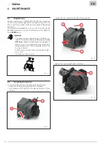
5.4
Adjustment
The burners leave the factory calibrated as shown in the pa-
ragraph “Factory calibration”, but during installation they nor-
mally require some adjustments to the settings described be-
low, which must be carried out while the burner is operating.
The adjustments must be made exclusively by the Sime Techni-
cal Service or by professionally qualified personnel.
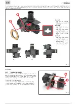
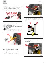
To adjust the position of the air shutter, use the Allen key (1)
provided and turn the screw (2):
– clockwise to increase the shutter’s opening (O
2
increases,
CO
2
decreases;
– anti-clockwise to decrease the air shutter’s opening (O
2
de-
creases, CO
2
increases).
O
2
+
CO
2
-
O
2
-
CO
2
+
1
2
Fig. 30
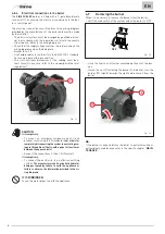
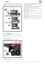
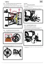
5.5
Pump pressure adjustments
To adjust the pump pressure and thus the burner’s power
output:
– remove the screw (8) and connect a pressure gauge (if it has
not been done previously);
– turn the screw (7) until reaching the desired pressure value,
which appears on the pressure gauge 7-15 bar.
NB.
After modifying the fuel pressure value, we suggest leaving the
burner running for a few minutes to stabilise the new condi-
tions. Subsequently, measure the combustion parameters (CO,
CO
2
and the smoke index - The CO must not exceed 50ppm). If
the values are as desired, stop the appliance and restore the
initial conditions.
If not, repeat the procedure described.
8
4
7
Fig. 31
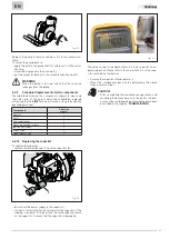
5.6
Checking the pump’s negative pressure
To make sure that the pump can work properly we suggest ve-
rifying the negative pressure value during suction. To do this,
remove the screw (4) (if this has not been done previously) and
install a vacuum gauge on which to read the negative pressure
value.
The maximum allowed negative pressure is
0,4 bar
.
NB.
With a negative pressure higher than 0,4 bar, diesel turns into
gas, causing cavitation of the pump and resulting damages to
the latter. Check the entire fuel intake line, including the filter
on the line and the one (H) inside the pump.
H
Fig. 32