116
EN
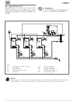
8.9
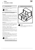
Electrical connections for the cascade
The electrical connections between the
Sime
ALU HE
boilers
which make up the cascade are shown in the following diagram,
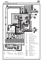
and the wiring diagrams for the individual appliances are shown
on the next few pages.
m
WARNINGS
The manufacturer is not responsible for any damage
caused by failure to earth the appliance or failure
to observe the information provided in the wiring
diagrams.
m
WARNINGS
–
The external temperature sensor “SE” is OBLIGATORY
and MUST be connected to the master boiler
.
– The cascade delivery probe “SMC” MUST be
connected to slave boiler no. 1.
BOILER BOARD (MASTER)
BOILER BOARD (SLAVE 1)
BOILER BOARD (SLAVE ...)
EXTERNAL SENSOR (SE)
CASCADE DELIVERY PROBE (SMC)
MODBUS INTERFACE KIT Code 8092278
OT
1
2
3
1
2
CABLE CHARACTERISTICS:
- 2 wires with cross-section of at least AWG24 - Shielded and twisted - Characteristic impedance of at least 100 - Shielding connected to the earth on one side of the line only
ISPESL SAFETY KIT (Italy only)
Pmin
Pmax
TS
External supervision (in MODBUS)
12
34
56
–
+
GND
–
+
GND
BLACK GREEN BLUE RED
12
34
56
–
+
GND
–
+
GND
BLACK GREEN BLUE RED
BOARD RS-485
BOARD RS-485
12
34
56
–
+
GND
–
+
GND
BLACK GREEN BLUE RED
BOARD RS-485
Fig. 48
Summary of Contents for ALU HE 116
Page 6: ...6 IT ...
Page 12: ...12 IT ...
Page 24: ...24 IT ...
Page 61: ...61 IT ...
Page 62: ...62 EN ...
Page 66: ...66 EN ...
Page 72: ...72 EN ...
Page 84: ...84 EN ...
Page 121: ...121 EN ...
Page 122: ...122 ...
Page 123: ...123 ...


