


17
EN
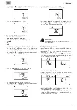
2.12 Electrical connections
The power cable must be connected to a 230V (±10%) ~ 50 Hz
network, observing L-N polarity and the earth connection. The
network must have an omnipolar switch with category III over-
voltage, in compliance with the installation rules.
If this cable needs to be replaced, an original spare must be re-
quested from
Sime
.
Therefore only the connections of the original components as
shown in the table are needed. These are to be ordered sepa-
rately from the boiler.
DESCRIPTION
CODE
External sensor kit (ß=3435, NTC 10KOhm at 25°C)
8094101
Power cable (dedicated)
6323875
Remote control HOME (open therm)
8092280
Remote control HOME PLUS (open therm)
8092281
m
CAUTION
The maintenance interventions described must ONLY
be carried out the professionally qualified personnel.
a
WARNING
Before carrying out any interventions described:
– set the main system switch to "OFF"
– close the gas valve
– make sure that no hot parts inside the appliance are
touched.
OFF
Fig. 18
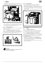
To facilitate introduction of the connection wires of the optional
components into the boiler:
– remove the screws (1), pull the front panel (2) forwards and
release it from the top by lifting it
1
2
Fig. 19
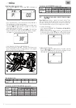
– remove the screws (3) securing the control panel (4)
– move the panel (4) upwards (a) but keeping it in the side
guides (5) to the end of travel
– bring it forwards and down (b) until it is horizontal
3
a
b
5
4
Fig. 20
– insert the connection wires into the cable gland (6) and the
opening (7) on the control panel
6
7
Fig. 21
– bring the control panel (4) to the original position and secure
it with the screws (3) which were removed previously
– connect the component wires to the terminal board (8) follow-
ing the indications provided on the data plate (9).
3
4
8
9
SE
TA
SAUX
6
5
4
3
2
1
Fig. 22