


8.2 Debug Modes
The kit can be used in various debug modes as explained in this chapter. The on-board debugger can be used to debug the EFR32 on
the radio board, or it can be used to debug a supported external target board using either the debug connector or the Mini Simplicity
Connector. An external debugger can furthermore be used to debug the EFR32 on the radio board using the debug connector. Select-
ing the active debug mode is done in Simplicity Studio.
Note:
The Wireless Starter Kit Mainboard (BRD4001A) does not feature a Mini Simplicity Connector; therefore, debugging an external
target board directly over the Mini Simplicity Connector is not supported on this mainboard. However, it is possible to debug an external
target that uses a Mini Simplicity Connector from the Wireless Starter Kit Mainboard by using a BRD8010A STK/WSTK Debug Adapter.
Debug MCU:
In this mode, the on-board debugger is connected to the EFR32 on the kit. To use this mode, set the debug mode to
[
MCU
].
RADIO BOARD
Board
Controller
USB
Host
Computer
DEBUG HEADER
External
Hardware
Figure 8.1. Debug MCU
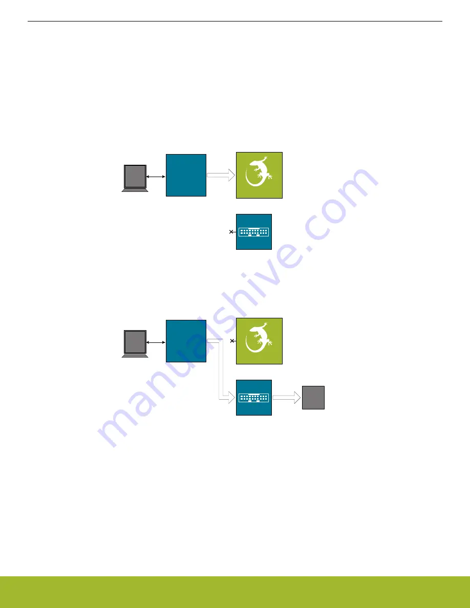
Debug OUT:
In this mode, the on-board debugger can be used to debug a supported Silicon Labs device mounted on a custom board
using the debug connector. To use this mode, set the debug mode to [
Out
].
Board
Controller
USB
Host
Computer
DEBUG HEADER
External
Hardware
RADIO BOARD
Figure 8.2. Debug OUT
Debug IN:
In this mode, the on-board debugger is disconnected and an external debugger can be used to debug the EFR32 on the kit
over the debug connector. To use this mode, set the debug mode to [
In
].
UG525: EFR32xG24 2.4 GHz 10 dBm Wireless Pro Kit User's Guide
On-Board Debugger
silabs.com
| Building a more connected world.
Rev. 1.0 | 32


