

You can install the controller-drive tray into an industry-standard
cabinet.
There must be a minimum depth of 76 cm (30 in.) between the front
EIA support rails and the rear EIA support rails.
Position the mounting rails in the cabinet.
•
If you are installing the mounting rails above an existing tray,
position the mounting rails directly above the tray.
•
If you are installing the mounting rails below an existing tray,
allow 8.9-cm (3.5-in.) vertical clearance for the E5512 controller-
drive tray.
Starting with the left mounting rail, use a fl at-blade screwdriver to
loosen the two fl at-head rail adjustment screws. Hold the front of
the left mounting rail against the inside of the front cabinet-mounting
fl ange, and then extend the rear of the mounting rail until it makes
contact with the rear cabinet-mounting fl ange. The alignment pins at
the rear of the mounting rail should slide into the holes at the rear of
the cabinet.
2.2
Install the mounting rails
2
2.1
Before you begin
1
Options:
•
Drives (two minimum for each controller-drive tray)
•
Ethernet cable (for out-of-band storage array management)
•
Two QSFP transceivers for each optical cable
•
Two host channel adapters (HCAs), or two Infi niband adapters
installed in each host
•
Two SAS copper cables for each drive tray connection
If you have any questions about the fi rmware or your confi guration,
contact your Technical Support representative.
Tools:
•
A cart to hold the controller-drive tray and its components
•
Labels for the cable connections
•
A
medium
fl at-blade screwdriver
•
A No. 2 Phillips screwdriver
•
Anti-static
protection
•
A
fl ashlight
For warnings, refer to the printed
Safety
Notices
document.
For detailed installation instructions, refer to
E5500 Controller-Drive
Tray and Related Drive Trays
hardware installation guide.
For more information, refer to the
Initial Confi guration and Software
Installation Guide for SANtricity™ ES Storage Manager
.
What you need for assembly:
E5512 controller-drive tray:
•
One two-unit (2U) -high E5512 controller-drive tray
•
Two power cords
•
Four Small Form-factor Pluggable (QSFP) transceivers, one for
each of the host channel ports on the controllers (IB only)
•
One cabinet mounting hardware kit, including:
–
Two mounting rails (right and left assemblies)
–
Eight M5 x 8 mm screws – Use six screws to secure the
mounting rails and two screws to secure the front of the
controller-drive tray to the cabinet.
–
Two M4 x 8 mm screws – Use the screws to secure the rear
of the controller-drive tray to the mounting rails.
1.1
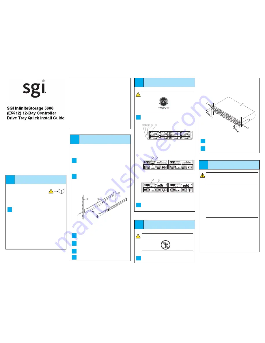
1 Mounting Holes on the Industry-Standard Cabinet
2 Adjustment Screws for Locking the Length of the Mounting Rail
3 Mounting Rail
4 Clip for Securing the Rear of the Controller-Drive Tray
From the front of the cabinet, with the mounting-rail fl anges inside of
the cabinet’s mounting rail assemblies, use the Phillips screwdriver to
loosely tighten only the lower screw.
From the rear of the cabinet, use the Phillips screwdriver to loosely
tighten the two screws. Do not completely tighten the screws until you
have installed the controller-drive tray in the cabinet.
Repeat step 2.2 through step 2.4 for the right mounting rail.
Tighten the fl at-head rail adjustment screws on both mounting rails.
2.3
2.6
2.5
2.4
4.2
4.3
Secure the rear of the controller-drive tray to the cabinet by using two
screws to attach the fl anges on each side at the rear of the controller-
drive tray to the mounting rails.
Install the front end caps on the front of the controller-drive tray by
pressing the front end caps into place on the left side and the right side.
E5512 Controller-Drive Tray – Front View
1 Standby Power LED
2 Power LED
3 Over-Temperature LED
4 Service Action Required LED
5 Locate LED
6 Drive Canister
E5512 Controller-Drive Tray – Rear View with SAS HIC
1 Controller Canister
2 Power-Fan Canister
30013-01
AC
DC
!
AC
DC
!
1
2
!
1
2
3 4
5
6
E5512 Controller-Drive Tray
2
1
2
1
1 Mounting Holes
2 Screws
Connect the cables
5
WARNING (W03) Risk of exposure to laser radiation
– Do not
disassemble or remove any part of a Small Form-factor Pluggable
(SFP) transceiver because you might be exposed to laser radiation.
ATTENTION Potential damage to equipment (Network
Telecommunications Equipment (NEBS) Ethernet cable
installations only) –
The intra-building port(s) (Ethernet maintenance
ports) of this equipment is suitable for connection to intra-building
or unexposed wiring or cabling only. The intra-building port(s) of
this equipment must not be metallically connected to interfaces that
connect to the Outside Plant (OSP) or its wiring. These interfaces
are designed for use as intra-building interfaces only (Type 2 or Type
4 ports as described in GR-1089-CORE) and require isolation from
the exposed OSP cabling. The addition of Primary Protectors is not
suffi cient protection in order to connect these interfaces metallically
to OSP wiring.
The cable shall be Shielded Twisted Pair (STP) and must be grounded
at both ends to meet the intra-building lightning requirements from
section 4.6.9.2 of GR-1089-CORE, Issue #5.
In this step, you will connect the E5512 controller-drive tray to the
host or hosts, and then you will connect the DE5600 drive tray or
the DE1600 drive tray to either a E5512 controller-drive tray (which
contains the controllers), or to another DE5600 drive tray or DE1600
drive tray in the storage array (step 5.5). For more information, refer
to these documents:
•
Quick Install Guide for the DE5600 Drive Tray
•
Quick Install Guide for the DE1600 Drive Tray
•
Quick Install Guide for the DE6600 Drive Tray
•
E5500 Controller-Drive Tray and Related Drive Trays
hardware
installation guide
3.2
E5512 Controller-Drive Tray – Rear View with Infi niBand HIC
AC
DC
!
AC
DC
!
30013-02
1
2
1 Controller Canister
2 Power-Fan Canister
With the help of one other person, slide the rear of the controller-drive
tray onto the mounting rails so that the mounting holes on the front
fl anges of the controller-drive tray align with the mounting holes on the
front of the mounting rails.
3
Install the
controller-drive tray
WARNING (W08) Risk of bodily injury
Two persons are required to safely lift the component.
With the help of one other person, remove the controller-drive tray from
the shipping box.
3.1
4
Secure the
controller-drive tray
WARNING (W18) Risk of bodily injury
– Do not use equipment in
the cabinet as a shelf or workspace.
4.1
Secure the screws in the top mounting holes and the bottom mounting
holes on each side of the controller-drive tray (refer to the image at the
top of the next column).
You will install the DE5600 drive trays and the DE1600 drive
trays below and above the controller-drive tray, keeping the
weight in the lower portion of the cabinet. For the maximum
number of drives supported in a particular confi guration,
see the
E5500 Controller-Drive Tray and Related Drive Trays
hardware installation guide.


