UNOCODE 299
Operating manual - English
34
Copyright Silca 2002
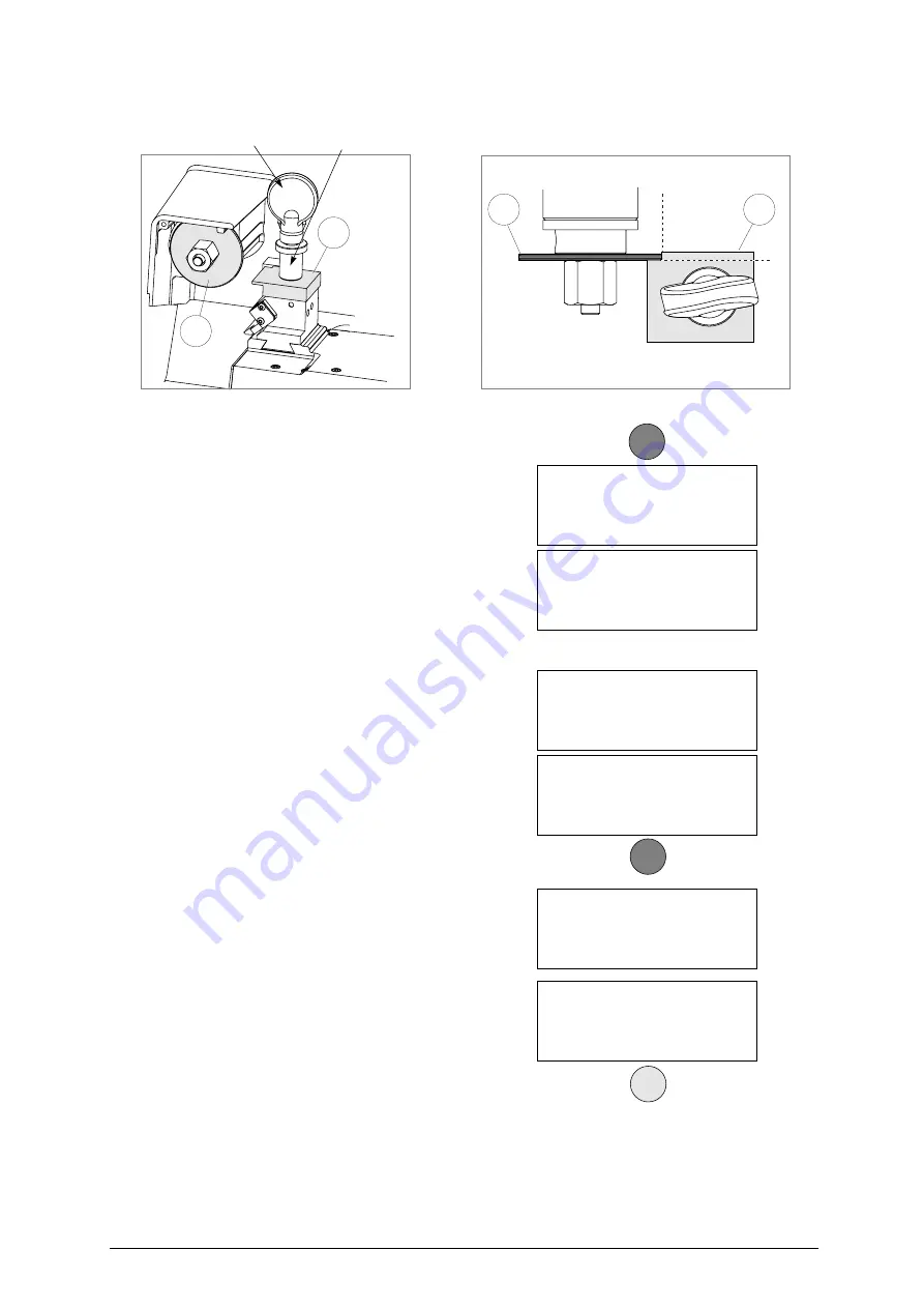
Fig. 26
Regulating the Y axis sensor:
•
raise the protective shield.
•
use the provided allen key to loosen the (C1)
grub screw; manually rotate the (C2) rod (fig.
27) in both directions up until the changeover
point from OFF to ON is found.
•
tighten the (C1) grub screw (fig. 27) to
secure the rod.
Regulating the X axis sensor:
•
carefully tip the machine over.
•
remove the bottom panel by unscrewing all 8
securing screws.
•
loosen the (C3) screw (fig. 28, page 35) that
secures the sensor support plate. Manually
move the sensor support plate up until the
display’s description goes from OFF to ON.
•
tighten the (C3) screw (fig. 28, page 35) to
secure the plate back into place.
•
re-position the machine back on its
workbench and lower the protective shield.
•
press START.
-
the ‘machine’s zero’ settings are de-
tected by electric contact.
8) when the operation has been completed,
the display will show the measured quotes.
9) press ENTER to save the settings.
ATTENTION: if the STOP key is pressed, the new settings
will be lost. If so, only the previous setting
values will remain valid.
Z2
Z1
Z2
Y
X
Z2
Z1
top view
clamp’s knob
clamp’s bushing
Pos. sensors.
ICX = OFF
ICY = OFF
See operating manual.
[START]
Pos. sensors.
ICX = OFF ICY = OFF
See operating manual.
[START]
Pos. sensors.
ICX = ON ICY = ON
See operating manual.
[START]
Pos. sensors.
ICX = OFF
ICY = ON
See operating manual.
[START]
Zero detection
in progress!
Measured quotes:
X = 4444 Y = 3333
Save measurements?
No = STOP Yes = ENTER
ENTER
START
START
Summary of Contents for Unocode 299
Page 1: ...D425337XA vers 6 0 Operating manual...
Page 62: ......
Page 64: ...Operating manual English UNOCODE 299 Copyright Silca 2002 Appendix IV...
Page 65: ...Operating manual English UNOCODE 299 Copyright Silca 2002 Appendix V...
Page 66: ...Operating manual English UNOCODE 299 VI Appendix Copyright Silca 2002...


