background image

General


MC 75.2  

- 14 - 


© SIKA  

  Ba_MC75.2_en  

  03/2017  

1.3.1


User Interface 


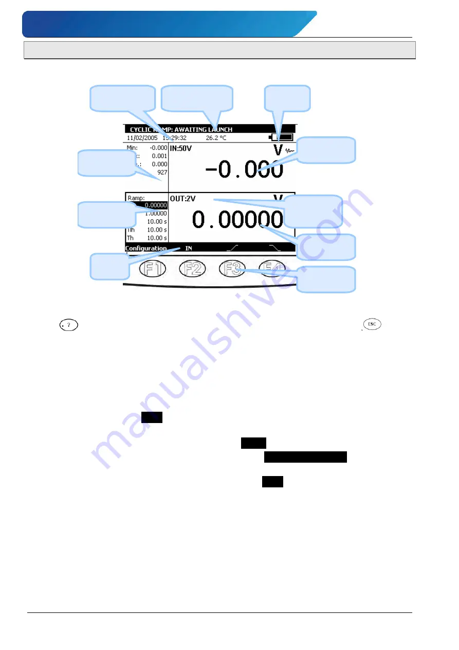
The basic items forming the user interface are shown in the diagram below: 


Date, Time & 

Temperature 

Description of the 

current function 

Battery 

state 


Measurement 

 Statistics 

Transmission 

Parameters  

Main 

Menu  

Measurement 

information 


Emission 

Information 


Distinction 

between IN 

and OUT 

Function 

keys


The "on-line help" function is not visible in the menu, but is accessible at any time by press-
ing the 

 key. When active, a help window for the function in use appears. The 

 key 

closes the help window and all the dialogue boxes displayed. 


The main menu is located at the bottom of the screen, opposite the four function keys (F1 to 
F4). To select an item from the menu, press the associated function key. 


Navigation within menus and sub-menus is by means of the navigation keys and the ENTER 
key. 
For example, to display the 

% FS

 menu in the example of the screen below, perform the fol-

lowing steps: 


1. Press the F4 key associated with the proposed 

 Mode

 from the main menu. 


2. Press the Down 

 navigation key twice to select the 

Predefined settings

 sub-menu and 

confirm with the ENTER key. 


3. Press the Down navigation key 

 once to select the 

% FS

 sub-menu and confirm with 

the ENTER key. A dialogue box associated with this function appears and the four func-
tion keys change their function automatically to suit the dialogue box. 


It is possible to cancel the selection at any time and return to the main menu by pressing the 
ESC key. 


Summary of Contents for MC 75.2

Page 1: ...ing manual for future reference If the device is resold please provide the operating manual along with it SIKA Ba_MC75 2_en 03 2017 Multifunction simulator Type MC 75 2 Operating manual Translation Operating manual page 1 64 ...

Page 2: ...1 4 3 Making measurements 17 1 4 4 Unusual faults and stresses 18 1 4 5 Definitions 18 1 5 Service 19 1 5 1 Maintenance menu 19 1 5 2 Cleaning 19 2 Getting started 20 2 1 Powering on 20 2 2 Measurement 21 2 2 1 Voltage measurement DC 22 2 2 2 Current measuring DC 22 2 2 3 Resistance measuring 25 2 2 4 Continuity test 25 2 2 5 Frequency measuring signal 26 2 2 6 Frequency measuring dry contact 26 2...

Page 3: ...ions 50 3 7 Customer specific configurations 53 3 8 Instrument Setup 54 3 8 1 Contrast 54 3 8 2 Date and Time 54 3 8 3 Preferences 55 4 Technical Specifications 56 4 1 Measurement Function 56 4 1 1 Current measurement DC 56 4 1 2 Current measurement DC 56 4 1 3 Resistance measurement 57 4 1 4 Temperature measurement Thermocouples 57 4 1 5 Temperature measurement RTD 58 4 1 6 Frequency measurement ...

Page 4: ...al injuries that can lead to health defects or cause considerable damage to property CAUTION Material damage This sign indicates actions which could lead to possible damage to material or environmental damage ADHERE TO OPERATING MANUAL NOTICE This symbol indicates important notices tips or information NO DOMESTIC WASTE The device must not be disposed of to gether with domestic waste Pay attention ...

Page 5: ...at it will operate without interruption SIKA approved distributors shall apply this guarantee to products sold to new clients it has not served but are not authorised to offer a longer or different guarantee in the name of SIKA Guarantee support is offered if the product was purchased by an intermediary from an SIKA approved point of sale or if the purchaser has paid the applicable international p...

Page 6: ...usions of this guarantee may not apply to every purchaser If any condition of this guarantee is considered invalid or inapplicable by a competent court such a decision will in no way affect the validity or binding nature of any other condition Checks the package contents All MC 75 2 units are mechanically and electrically checked before delivery The necessary precautions have been taken to ensure ...

Page 7: ...multaneously with a double display In particular it can calibrate air conditioning systems or transmitters by generating a signal at the input to simulate a sensor and measuring the conversion current or voltage Internal software facilitates this operation but it is also useful in other applications notably in moni toring changes in physical quantities during processing transformation phenomena he...

Page 8: ...atteries Battery life 5 to 10 hours depending on the functions used Stand for table mounting Strap for carrying and on site use 240 x 320 pixel liquid crystal graphical display Choice of language for messages and programming the functions settings and pa rameters using a keyboard with 22 keys Back lit display controllable from a key on the keyboard with automatic switch off af ter a programmable t...

Page 9: ...IP54 1 2 3 Connection terminals Four terminals for connection for the measurement function IN two of which are re served for 3 or 4 wire connection when measuring resistance temperature with a resistive probe and current for a passive transmitter 2 2 Four connection terminals for the transmit simulate function OUT 2 2 3 The 8 terminals of the MC 75 2 are of the push lock type They accept 4 mm bana...

Page 10: ...n The MC 75 2 is fitted with an LCD graphical display which is backlit with white LEDs The res olution of the display is 240 x 320 pixels When the unit is in use the screen comprises A window displaying the programming of the measurement function parameters IN 2 2 A window displaying the programming of the parameters of the transmis sion simulation function OUT 2 2 3 A strip showing the various me...

Page 11: ...e referred to as F1 F2 F3 and F4 but are not labelled on the unit A navigator A cancel key A Start stop key for the unit and back lighting on off key A short push switches the unit on During operation a short push switches the back lighting on or off A long push of 2 seconds switches the unit off 12 alphanumeric keys for programming the parameters An LED to indicate the state of charge of the batt...

Page 12: ...d while the batteries are charging CAUTION The charger can be used with voltages of 230 VAC The charger is for indoor use only at an ambient temperature not exceeding 40 C 104 F Only use the mains adaptor supplied with the calibrator Replacing the battery pack To replace the battery pack contact your SIKA dealer 1 2 8 Sand and Strap The stand gives a good angle of view when the MC 75 2 is placed o...

Page 13: ...tasks that are continuously executed during operation of the MC 75 2 The Measurement task is responsible for the configuration post processing and dis play of measurements The Transmission task handles the various modes of simulation pre processing of set tings and the display Several tasks are dedicated to setting parameters and configuration management The maintenance task is responsible for cal...

Page 14: ... the screen opposite the four function keys F1 to F4 To select an item from the menu press the associated function key Navigation within menus and sub menus is by means of the navigation keys and the ENTER key For example to display the FS menu in the example of the screen below perform the fol lowing steps 1 Press the F4 key associated with the proposed Mode from the main menu 2 Press the Down na...

Page 15: ...mple to select the Type of scale field on the following screen press the key once The tabulation key functions cyclically so that the first item follows the last The Right navigation key can replace the tabulation key The function key is used to display a drop down list The key also closes an already open drop down list The Up and Down navigation keys are used to select an item from an open list C...

Page 16: ...eys Tabulation key Open a drop down list Close a drop down list Cancel the selected item Stop the current transmission Suspend the current transmission Commence or resume transmission Launch transmission in the increasing direction Launch transmission in the decreasing direction Transmit synthesised points in the order entered Transmit synthesised points in the reverse order Cancel the selection A...

Page 17: ...uring correct operation of the unit and protection against any false step that could damage the unit or make it unsafe to use The unit may when necessary be subjected to temperatures of between 10 C and 55 C without prejudicing safety 1 4 2 Instructions The unit is designed to be used in complete safety if the instructions given in the accompany ing documents are followed Any use apart from those ...

Page 18: ...nce measurements on a live circuit 1 4 4 Unusual faults and stresses Whenever it is believed that the protection has been damaged switch off the unit and ensure that it is not used prematurely The protection may have been damaged if for example There is obvious damage to the unit The unit is no longer able to make accurate measurements The unit has been stored under unfavourable conditions The uni...

Page 19: ... that all wires are disconnected from the unit Any adjustment maintenance or repair of an open MC 75 2 must be avoided as far as possi ble and if essential must be carried out by qualified personnel who are familiar with the risks involved 1 5 1 Maintenance menu This Menu is protected by a password and not accessible to the user Consult SIKA who will indicate the procedure to follow for maintenanc...

Page 20: ...The red LED lights while the battery pack is charging Wait until fully charged LED off before switching on the unit by pressing the start stop key for one second After starting the MC 75 2 is set by default to voltage measurement and voltage transmis sion Connect the Volts output to the Volts input as shown in the diagram below Check that the measurement displayed is the same as the simulated volt...

Page 21: ... IN A rectangle surrounds the top window on the screen To choose a measurement function press key F1 configuration Select the Function menu with the navigation keys and confirm with the ENTER key The MEASUREMENT CONFIGURATION dialogue box is displayed Connections in the measurement mode are made to the four IN terminals on the left half of the unit ...

Page 22: ...sured is connected between the V and COM terminals 2 2 2 Current measuring DC Display the MEASUREMENT CONFIGURATION dialogue box Select the Idc measurement function then the correct measurement range using the function and navigation keys Confirm with ENTER Depending on the range selected several modes of measurement are available Range 50 mA 4 20 mA 0 20 mA Resolution 1 µA 1 µA 1 µA Input impedan...

Page 23: ...terminals mA and COM When set to the square law scale the calibrator takes the square root of the input and dis plays the result as a percentage For example if the calibrator is connected to the output of a differential pressure transmitter it displays a result proportional to the flow rate If the input current x varies between a and b the scale is set according to the formula a b a x a b a y In t...

Page 24: ...on using the following icons to show loop power supply off to show loop power supply on to show square law scale to show HART compatibility IMPORTANT When the values measured are near the lower limit of the range 0 mA or 4 mA a small variation in the values measured translates into a more significant variation for the con verted values in because of the square law nature of the scaling ...

Page 25: ... wires the 3 conductors used must be of the same length of the same diameter of the same type of metal The MC 75 2 displays an icon showing the connections used for 2 wire for 3 wire or 4 wire to make the measurement The wiring arrangement is automatically detected by the calibrator 2 2 4 Continuity test Display the MEASUREMENT CONFIGURATION dialogue box Select the Continuity measurement function ...

Page 26: ...h measures the frequency by counting with respect to a very stable reference signal 2 2 6 Frequency measuring dry contact Display the MEASUREMENT CONFIGURATION dialogue box Select the Frequency measurement function then the type of input Dry Contact using the function and navigation keys Confirm with ENTER Connection is made between the Hz and COM terminals The hard contact frequency measurement i...

Page 27: ...ENTER Connection is made according to the number of wires of the resistive probe The following probes are available α being the temperature coefficient of the probe The resolution is 0 01 C for all the available resistive probes The MC 75 2 displays an icon showing the connections used for 2 wires for 3 wires or for 4 wires to carry out the measurement The wiring arrangement is automatically detec...

Page 28: ...unction Confirm with ENTER The thermocouples available are K T J E N U L S R B C PL Mo NiMo NiCo After a significant thermal shock it is recommended that the unit is left for the temperature to stabilise in order to use the internal cold junction CSF with maximum accuracy 2 2 10 Pressure measuring Display the MEASUREMENT CONFIGURATION dialogue box Select the Pressure measurement function using the...

Page 29: ...for more information on the transmission simulation part Display the MEASUREMENT CONFIGURATION dialogue box Select the Pressure measurement function using the function and navigation keys Confirm with ENTER To access the Switch Test mode press the function key F4 to select the Mode menu and then press ENTER Select the type of detection Open Close or Open and Close using the function and navigation...

Page 30: ...e lower window of the screen To select a Simulation function press the F1 configuration key Select the Function menu using the navigation keys and confirm with the ENTER key A TRANSMISSION CONFIGURATION dialogue box is displayed The connections in the Transmission mode are made to the four OUT terminals located on the right half of the unit The F2 Key is used to switch from OUT mode to IN mode ...

Page 31: ...age to be generated is connected between terminals V and COM 2 3 2 Current generation DC Display the TRANSMISSION CONFIGURATION dialogue box Select the Idc measurement function then the range using the function and navigation keys Confirm with ENTER Depending on the range selected several transmission modes are available Range 24 mA 4 20 mA 0 20 mA Resolution 1 µA 1 µA 1 µA Loop power supply no po...

Page 32: ...le 2 3 3 Resistance generation Display the TRANSMISSION CONFIGURATION dialogue box Select the Ohm measurement function Select the Idc measurement function then the range using the function and navigation keys Select the measurement current Confirm with ENTER The following ranges are available Range 40 Ω 400 Ω 4000 Ω Resolution 1 mΩ 1 mΩ 10 mΩ Measurement current 1 10 mA 0 1 1 mA or 1 10 mA 0 1 1 m...

Page 33: ... ms to avoid errors in consecutive measurements due to the response time of the resistance simula tion function 2 3 5 Temperature simulation Thermocouple Display the TRANSMISSION CONFIGURATION dialogue box Select the Tc transmission function then the appro priate type of thermocouple using the function and navigation keys Select the display unit Select the type of cold junction compensation CSF us...

Page 34: ...ct ed value The display units may be in Hz or Beats per minute BPM Connection of the frequency source generated is between the Hz and COM terminals 2 3 7 Frequency generation dry contact Display the TRANSMISSION CONFIGURATION dialogue box Select the Frequency transmission function then the range using the function and navigation keys Select the Type of Output Dry contact Confirm with ENTER The fol...

Page 35: ...ess ENTER or enter the Configuration menu then Pulse The parameters are Width the duration of the HIGH logic state in seconds Period the duration of the HIGH logic state and the LOW log ic state in seconds Number the number of pulses to be generated between 1 and 999 999 To commence pulse generation press Start During pulse generation a progress bar indicates the state of progress The function key...

Page 36: ...fault to the Manual editing mode To access the other modes select the Mode menu using function key F4 Select a transmis sion mode using the Up Down keys of the navigator and confirm with ENTER To exit a transmission mode and return to the default mode press the ESC key 3 1 1 Manual Editing In this mode the value to be transmitted may be entered directly using the alphanumeric keys The value entere...

Page 37: ...onfirm it 3 1 3 Predefined Settings This mode is available for the DC current transmission function for the 0 20 mA and 4 20 mA ranges only Two types of predefined settings are offered Valve Test and Percentage of full scale of FS In the case of valve test the predefined values are dis played in the left hand side of the transmission window The icon is displayed in the right hand side of the windo...

Page 38: ...s mode is active the icon appears in the transmission window The function key launches a cycle of increasing in crements and the function key launches a cycle of decreasing increments The default parameters of this mode are displayed on the left hand side of the transmission window To change these parameters press ENTER or use the Configura tion Mode menus The parameters of a staircase are L Minim...

Page 39: ...ed to launch an increasing ramp and the function key is used to launch a decreasing ramp The default parameters of this mode are displayed on the left hand side of the transmission window To change these parameters press ENTER or use the Configura tion Mode menus The parameters of a simple ramp are L Minimum amplitude of the signal H Maximum amplitude of the signal I Amplitude of the increment T D...

Page 40: ...the left hand side of the transmission window To change these parameters press ENTER or use the Configura tion Mode menus The parameters of a cyclic ramp are L Minimum amplitude of the signal H Maximum amplitude of the signal Tl Duration of a decreasing ramp Tlh Duration of an increasing ramp Th Duration of the high step Thl Duration of the low step No Number of cycles to be generated Delay Delay ...

Page 41: ...ssion window To change these parameters press ENTER or use the Configura tion Synthesiser Parameters The parameters of the synthesiser mode are First point no Number of the first point in a cycle Last point no Number of the last point in a cycle T The duration for which a point is transmitted No The number of polling cycles Delay Delay in seconds between launch and transmission of the first point ...

Page 42: ...The key commences or resumes generation An icon in the transmission window indicates sus pended generation It is possible to transmit points manually one by one using the navigation keys Use the Up and Down keys to select a point ENTER transmits the selected point and Left Right select and transmit the previous next point in the list immediately 3 1 8 Transmitter Mode This mode is used to transmit...

Page 43: ... the screen in the active window when Set to scale is active The Define menu is used to program up to 10 lines with 2 values X and Y f X In measurment X the value measured X the value displayed In transmission X the setting displayed Y the value transmitted The lines entered are sorted according to increasing X to set to scale a value X the unit searches for the 2 lines n and m n 1 that enclose it...

Page 44: ...ZERO function to cancel by measurement or programming a con stant or interfering value TARE function When one of the relative measurement functions is ac tive the symbol is displayed on the screen in the measurement window The ZERO Festlegen menu is used to program the Tare value positive or negative This value is subtracted from the measurements Value displayed Value measured Tare Value ...

Page 45: ...time of meas urement Display the MEASUREMENT CONFIGURATION dialogue box Select the Calibrated sensors measurement func tion using the function and navigation keys Confirm with ENTER Use the Up or Down arrow keys to adjust the parameters or select a new line to define a new sen sor Confirm with ENTER Fill in the information fields for the sensor To move from field to field use the function key F1 T...

Page 46: ...on at temperature T In the specific case where a single calibration point is given the behavior will differ according to whether the sensor is a thermocouple or a thermometric resistance In the case of a thermocouple the correction is a fixed voltage deviation In the case of a resistive probe the correction made is an R0 correction Sensors declared in this manner are added to the list of couple ty...

Page 47: ... 3 6 Display the MEASUREMENT CONFIGURATION dia logue box Select the Calibration procedure measurement function using the function and navigation keys Confirm with ENTER Use the Up or Down navigation keys to adjust the parameters or press the key F1 new to define a new procedure Confirm with ENTER Complete the information fields for the transmitter to be calibrated and define the input output types...

Page 48: ...rder in which the points Point 1 Point 2 Point 3 are de fined Two Way the settings are generated automatically in the order in which the points Point 1 Point 2 Point are defined and then in reverse order Point n Point n 1 Point 2 Point 1 Settling time The settling time field can be used to define the time in seconds between sending the set ting from the output of the MC 75 2 and making the measure...

Page 49: ...to confirm the calibration points one by one If the transmission mode has been defined as One Way or Two Way the procedure is executed automatically Press the function key F1 to store the calibration re port To display the calibration reports select the desired procedure and press the function key F2 Reports From the list select the report to be viewed and press the function button F1 View Calibra...

Page 50: ...e left and right navigation keys can be used to switch from one mode to the other Pressing the function key F4 MREC1 stores the current acquisition Pressing the key F3 Memory gives access to all the memory functions RUN Starts the storage of data as configured using the Pa rameters function The icon is shown in the Measure ments window STOP Stops the current storage operation PARAMETERS This can b...

Page 51: ...ys can be pressed to move the cursor and read off the abscis sa and ordinate values At this level the markers can be redefined in order to zoom in between these two new points In the X field enter a low value for the marker X1 press ENTER and then press the function key F2 X 1 In the X field enter a high value for the marker X2 press ENTER and then press the function button F3 X 2 Burst record sav...

Page 52: ...ing the user will be asked if this should be saved Burst record management can be used to view all bursts in memory At this level a burst can be renamed or one or more bursts can be deleted Statistics Shows the number of bursts in memory the number of free bytes and the number of measurements that can be saved ...

Page 53: ...e state of the unit use the Configuration File Save as menus Use the navigation keys to select a configuration Edit the name of the configuration to be saved with the alphanumeric keys and confirm with ENTER To recall a configuration from memory use the Configuration File Open menus Use the navigation keys to select a configuration Con firm with ENTER When loading a saved configuration the MC 75 2...

Page 54: ...set the date and time of the unit The Preferences sub menu is used to set the generic parameters which apply to all the functions performed by the MC 75 2 3 8 1 Contrast Use the Right and Left navigation keys to adjust the con trast of the display The MC 75 2 saves the setting made in its non volatile memory The unit uses the setting each time the unit is switched on 3 8 2 Date and Time To set the...

Page 55: ...sible choices HIGH Displays measurements with the highest possible resolution AVERAGE Displays one digit fewer compared with the HIGH resolution mode LOW Displays two digits fewer compared with the HIGH resolution mode Temperature units Used to select the temperature units either C F or K for measurements and simulation Lighting Used to set the on time of the lighting before it is switched off to ...

Page 56: ...y and long term stability over the period quoted 4 1 Measurement Function Measurement rate 0 5 s per measurement Maximum rated voltage in common mode 60 VDC or VAC 4 1 1 Current measurement DC Range Resolution Accuracy Notes 100 mV 1 µV 0 013 of rdg 3 µV Rin 10 MΩ 1 V 10 µV 0 013 of rdg 20 µV Rin 10 MΩ 10 V 100 µV 0 015 of rdg 200 µV Rin 1MΩ 50 V 1 mV 0 015 of rdg 2 mV Rin 1MΩ Temperature coeffici...

Page 57: ...tables of HOSKINS thermocouple C According to table of ENGELHARD thermocouple platinum Sensor Range of measurement Resolution Accuracy K 250 up to 200 C 200 up to 120 C 120 up to 0 C 0 up to 1372 C 0 2 C 0 1 C 0 05 C 0 05 C 0 80 C 0 25 C 0 1 C 0 013 of rdg 0 08 C T 250 up to 200 C 200 up to 120 C 120 up to 50 C 50 up to 400 C 0 2 C 0 05 C 0 05 C 0 05 C 0 70 C 0 25 C 0 10 C 0 013 of rdg 0 08 C J 21...

Page 58: ...rature of the terminals of the unit by programming the temperature 4 1 5 Temperature measurement RTD Sensor Range of measurement Resolution Accuracy Pt 50 α 3851 220 C up to 1200 C 0 01 C 0 012 of rdg 0 06 C Pt 100 α 3851 220 C up to 1200 C 0 01 C 0 012 of rdg 0 05 C JPt 100 α 3916 200 C up to 510 C 0 01 C 0 012 of rdg 0 05 C Pt 100 α 3926 210 C up to 850 C 0 01 C 0 012 of rdg 0 05 C Pt 200 α 3851...

Page 59: ...range selection For the mV V and Ω functions with automatic range selection the unit selects a higher or lower range Relative measurement The relative measurement function is used to programming a reference value other than that of the unit ZERO function cancel by measurement or programming a constant or interfering value TARE function Scale correction The scale correction function performs a conv...

Page 60: ...A 0 20 mA 1 µA 0 0175 of rdg 2 µA Temperature coefficient 10 ppm C from 0 C to 18 C and from 28 C to 50 C Settling time 5 ms 4 2 3 Resistance generation Range Resolution Precision 1Year Notes 40 Ω 1 mΩ 0 014 of rdg 3 mΩ 0 014 of rdg 10 mΩ Iext von 10 mA Iext von 1 mA 400 Ω 10 mΩ 0 014 of rdg 20 mΩ 0 014 of rdg 30 mΩ Iext von 1 mA up to 10 mA Iext von 0 1 mA up to 1mA 4000 Ω 100 mΩ 0 014 of rdg 300...

Page 61: ...200 up to 600 C 0 05 C 0 15 C L 200 up to 900 C 0 05 C 0 20 C C 20 up to 900 C 900 up to 2310 C 0 1 C 0 1 C 0 25 C 0 013 of rdg 0 15 C N 240 up to 190 C 190 up to 110 C 110 up to 0 C 0 up to 1300 C 0 2 C 0 1 C 0 05 C 0 05 C 0 3 C 0 15 C 0 08 C 0 013 of rdg 0 06 C Platinum 100 up to 1 400 C 0 05 C 0 3 C Mo 0 up to 1375 C 0 05 C 0 013 of rdg 0 06 C NiMo NiCo 50 up to 1410 C 0 05 C 0 013 of rdg 0 30 ...

Page 62: ...or negative temperatures use the displayed value L and not its absolute value Temperature coefficient 10 of the accuracy C The above accuracy is given for 4 wire connection of the temperature sensor Taking into account also the intrinsic error of the temperature sensor used and its con ditions of use Measurement current from 0 01 mA to 1 mA Settling time 1 ms 4 2 6 Frequency and pulses generation ...

Page 63: ...eration of ramps The ramp generation function is used to program a linear variation of the active transmission function Synthesiser The synthesiser function is used to store up to 100 transmission values in permanent memory to recall and transmit manually or automatically the contents of these memories Scale correction The scale correction function performs a conversion between the physical quanti...

Page 64: ...3 2017 Sensors and Measuring Instruments Flow Measuring Instruments Test and Calibration Instruments SIKA Dr Siebert Kühn GmbH Co KG Struthweg 7 9 D 34260 Kaufungen Germany 49 0 5605 803 0 49 0 5605 803 54 info sika net www sika net ...

Reviews: