Rev. 5.1 February 4, 2008
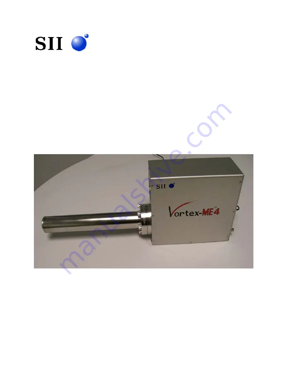
Vortex-ME4™
Multi-Element Silicon Drift Detector X-Ray Spectrometer
User’s Manual
SII NanoTechnology USA Inc.
19865 Nordhoff Street
Northridge, CA 91324
Phone (818) 280-0745
Fax (818) 280-0408
Page 1: ...5 1 February 4 2008 Vortex ME4 Multi Element Silicon Drift Detector X Ray Spectrometer User s Manual SII NanoTechnology USA Inc 19865 Nordhoff Street Northridge CA 91324 Phone 818 280 0745 Fax 818 280 0408 ...
Page 2: ... is the property of SII NanoTechnology USA Inc SNTUS and may not be copied or reproduced in any manner or form without the prior written consent of SNTUS This manual and the data herein are subject to change at any time without notification ...
Page 3: ...4 3 2 Power supply PS electronics box 6 3 3 Preamplifiers 7 4 Operation 9 4 1 Setting up for operation 9 4 2 Powering down the system 10 4 3 Turning the system ON OFF when not in use 10 5 Trouble Shooting 10 5 1 The spectrum cannot be acquired 10 5 1 1 Preamplifier does not ramp up in voltage 11 5 1 2 Preamplifier output is always positive 11 5 2 Poor energy resolution and or noisy 11 6 Technical ...
Page 4: ...e snout is facing down Do not mount the SDD package into a position such that the detector end of the snout is tilted up The system can be stored at room temperature without any special care but it is recommended that it be stored in a location with low humidity List of items delivered SDD package Digital Pulse Processor and or Power Supply Main biasing cable 12 V DC wall transformer User s Manual...
Page 5: ...ly rare and would not be expected to be encountered under normal operating conditions in a laboratory environment However if you suspect you are observing electro magnetic interference effects please contact technical support at SNTUS to determine the solution 3 System Description The system is comprised of three main parts as shown in Figure 1 the SDD package the power supply PS box and cable Fig...
Page 6: ...or power supply and the BNC connectors are for the signal output The test point T is for the SDD temperature testing The power jack is for the external 12 V DC wall transformer that supplies the ion pump power The test point IP is for measuring the current of the ion pump The LED is lit when power is supplied to the ion pump from the external 12 V DC wall transformer Figure 2 Vortex ME4 SDD packag...
Page 7: ...wer supply PS electronics box The PS electronics box includes the detector power supply that provides four separate voltages to bias the SDDs and power supplies that provide power to the TEC and to the rest of the electronics The front and the back panels of the PS electronics box are shown in Figures 5 and 6 respectively The PS box has external dimensions of 220 2 x 152 4 x 87 63 mm3 L x W x H an...
Page 8: ...tector cooling process is complete and the detector is functioning normally On the back panel of the PS electronics box Figure 6 are the ON OFF switch the detector power connector and the detector bias test points 3 3 Preamplifiers There are four preamplifiers one for each SDD The preamplifier is a charge sensitive preamplifier which is optimized to work with a transistor reset FET All four preamp...
Page 9: ... 5 mV per 1 keV photon energy as is shown in Figure 8 The mV keV ratio can be modified per the customer s request if required With an x ray source applied the preamplifier output signal consists of positive steps superimposed on an irregularly spaced ramp of positive slope as is shown in Figure 8 The negative reset duration is about 1 µs Figure 8 Oscilloscope trace of preamplifier output step puls...
Page 10: ...point voltage is less than 0 3 V 4 1 Setting up for operation Connect the appropriate ends of the cables to the preamplifier box back panel connectors shown in Figure 9 Figure 9 Vortex ME4 SDD package and PS electronics box Main biasing cable connects to the D Sub 15 pin connector including Detector Bias TEC and preamplifier power Output cables to Preamps Out Connect the other end of the cables to...
Page 11: ...h most electronic systems there is a momentary recharging process that takes place after rebooting the system It is therefore important to wait 3 minutes before turning the system back ON Note Unless it is absolutely necessary avoid turning the detector OFF after turning it ON for at least 3 minutes past reaching its stable operating temperature 5 Trouble Shooting 5 1 The spectrum cannot be acquir...
Page 12: ...eturn the system for repair Poor energy resolution may also occur if the correct biases are not being supplied to the detector in which case you should also contact SNTUS 6 Technical Support Please contact SII NanoTechnology USA Inc SNTUS for technical support or additional information 818 280 0745 7 Inspection and Acceptance Purchaser shall inspect all products immediately upon delivery and shall...
Page 13: ...D PERFORMED ON THE PRODUCTS WITHOUT LIMITING THE FOREGOING IT IS EXPRESSLY UNDERSTOOD AND AGREED THAT EACH AND EVERY PROVISION OF THIS DOCUMENT THAT PROVIDES FOR A LIMITATION OF LIABILITY DISCLAIMER OF WARRANTIES OR EXCLUSION OF DAMAGES IS INTENDED TO BE SEVERABLE AND INDEPENDENT OF ANY OTHER PROVISION AND TO BE ENFORCED AS SUCH FURTHER IT IS EXPRESSLY UNDERSTOOD AND AGREED THAT IN THE EVENT ANY R...