background image

Instruction Manual AquaMaster 

Servicing 

74 

12745E/4 


8.1.5


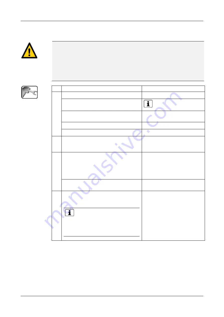
Clean and calibrate Conductivity sensor 


CAUTION! 

The Conductivity sensor can be damaged through improper handling. 

The Conductivity sensor can be damaged by carelessly touching the measuring tip or by us-
ing the wrong cleaning agent. 


For cleaning and calibrating this sensor please consult Section 8.1.1. 


Touch the Conductivity sensor only if absolutely necessary. 


Do not clean with abrasive cleaning agents.  


Use only recommended cleaning agents for cleaning.  


WORKSTEP 

ADDITIONAL INFO / IMAGES 

1. 

1.1: Press the 

Menu

 button. 


1.2: Set access code and confirm with 

OK

 Factory setting is 

0

1.3: Press button with 

(S1 .. S4) name of the 

conductivity sensor


1.4: Select the 

Recalibration

 menu. 


1.5: Select 

C1 Conduct.

 menu. 


2. 

Remove Conductivity sensor in accordance 
with Section 8.1.2 and position in the locking 
device.  


3. 

Clean measuring tip of the sensor. 

3.1: Dip the measuring tip into cleaning solu-
tion or dab with a soaked cloth. 

Use cleaning agents in accordance with Section 
8.1.1.3. 


3.2: Rinse the measuring tip with distilled wa-
ter and dab dry. 


4. 

Prepare recalibration. 

4.1: Open calibration holder and fill with buffer 
solution by pressing the container. 

 Calibration solutions from various 

manufacturers are supported. They can be 
selected in the 

Recalibr./Cali. standard


menu. The one from Hamilton is set as stan-
dard. 


Summary of Contents for AquaMaster

Page 1: ...Document number 12745E Version 4 Valid from S N 281085 SW V128 INSTRUCTION MANUAL AquaMaster with AquaScat 2 WTM WTM A HT Multi Parameter Measuring System ...

Page 2: ...ST PHOTOMETER AG subject to technical changes without notice 7 2017 SIGRIST PHOTOMETER AG Hofurlistrasse 1 CH 6373 Ennetbürgen Switzerland Tel 41 41 624 54 54 Fax 41 41 624 54 55 info photometer com www photometer com ...

Page 3: ...afety points 22 3 1 Dangers when using properly 22 3 2 Preventing undesirable online access attempts 23 3 3 Residual risk 24 3 4 Warning and danger symbols on the instrument 24 4 Mounting and installation 25 4 1 Safety pointers for electrical connection 25 4 2 Location selection 25 4 3 Mount base plate 26 4 4 Connecting the connection box 27 4 5 Position of the connection box 29 4 6 Fasten photome...

Page 4: ...d calibrate Redox ORP sensor 77 8 1 7 Cleaning and calibrating the oxygen sensor 80 8 1 8 Replace sensors configured by SIGRIST 81 8 1 9 Installing an unconfigured sensor 82 8 1 10 Clean the measuring cell block 84 8 1 11 Cleaning the tubing 85 8 2 Servicing schedule for AquaScat 2 WTM WTM A HT 86 8 2 1 Fastening the optics unit to the docking station 87 8 2 2 Checking the flow rate and cleanlines...

Page 5: ...Contents Instruction Manual AquaMaster 12745E 4 5 14 Spare parts list 117 14 1 Spare parts for the AquaMaster 117 14 2 Spare parts for the AquaScat 2 WTM A HT 117 15 Appendix 118 16 Index 120 Makro ...

Page 6: ...Instruction Manual AquaMaster Contents 6 12745E 4 This page is intentionally blank Makro ...

Page 7: ...sible for the operation and maintenance of the instrument 1 4 Additional documentation DOC NO TITLE CONTENT 12748E Brief Instructions The most important functions and the servicing schedule 12749E Reference Handbook Menu functions in depth and worksteps for ad vanced users 12756E Data Sheet Descriptions and technical data about the photo meter 12831DEF Declaration of Con formity Compliance with th...

Page 8: ...ly by trained technical personnel who have read and un derstood the content of the Instruction Manual 1 10 Declaration of conformity Current technological principles were followed in designing and manufacturing the instru ment They comply with the applicable guidelines concerning safety and duty to take due care EU The measuring instrument meets all applicable requirements within the European Unio...

Page 9: ... expressly recommended Improper changes to the instrument have been performed The instrument has not been operated within the specifications in particular concerning pressure and temperature 1 13 Meaning of the safety symbols All danger symbols used in this document are explained below DANGER Danger due to electrical shock that may result in serious bodily injury or death Non observance of this da...

Page 10: ...aning of the pictograms All pictograms used in this document are explained below Additional information about the current topic Practical procedures when working with the AquaScat Manipulations on the touchscreen The screenshot is an example and may differ from current device ...

Page 11: ...TM WTM A HT Flow Regulator valve for photometer Measuring cell block cover with docking station for photometer Inlet flow regulator valve for measuring cell block Sight glass for flow rate to measur ing cell block Sight glass for photometer overflow Measuring cell block with sensors for Redox ORP Oxygen pH Con ductivity Outlet regulator valve for measuring cell block Sample medium inlet Sample med...

Page 12: ...hotometer The photometer is fitted with the following rating plate Figure 2 Rating plate on AquaScat 2 WTM A Manufacturer Country of origin Product name Serial number Date of manufacture Service voltage Frequency range Power Observe the Instruction Manual Observe the disposal information ...

Page 13: ...e connection box The rating plate below is located on the connection box Figure 3 AquaMaster rating plate connection box Manufacturer Country of origin Product name Serial number Date of manufacture Service voltage Frequency range Power Observe the Instruction Manual Disposal information ...

Page 14: ...om plete with tubing holder and meas uring cell block 1 For 119490 with Aqua Scat 2 WTM For 119491 with Aqua Scat 2 WTM A For 119492 with Aqua Scat 2 HT Photometer AquaScat 2 WTM WTM A HT with in tegrated I O module 1 Included in the scope of supply of 119490 1 2 Connection box with all cables 1 Included in the scope of supply of 119490 1 2 Wash bottle 1 Included in the scope of supply of 119490 1...

Page 15: ...E VIEW VARIANT 1 119423 One deaeration tube optional 1 119424 Two auxiliary de aeration tube optional 1 116708 Checking unit for AquaScat 2 WTM HT Manual solid refer ence 1 119542 Flow meter 1 119543 Flow meter with limit switch 1 119566 Regulating valve 1 119102 Profibus DP inter face print Reference handbook 1 119103 Modbus RTU inter face print Ref erence handbook 1 119798 HART interface print R...

Page 16: ...7 μ cm 500 ml 1 119495 pH sensor Sensor for measur ing the pH value Polilyte Plus Arc 120 Two calibration solutions are sup plied If no specific specifications are given this is pH 4 and pH 7 Calibration standards 119506 pH 7 119507 pH 10 119571 pH 4 1 119497 Oxygen sensor Sensor for measur ing dissolved oxy gen VisiFerm DO Arc 120 1 119496 Redox ORP sensor Sensor for measur ing the redox potentia...

Page 17: ...18 30 VDC Power consumption 10W AquaMaster 4 Sensors 25W AquaMaster 4 Sensors optional Photometer Weight ca 16 kg Protection class IP 54 Maximum operating altitude No limitation when powered with 24 VDC also the relay voltages do not exceed 24 V 2000 m 6600 ft above sea level if powered with 250 V Ambient temperature 0 50 C Ambient humidity 0 100 rel humidity noncondensing Sample pressure 0 6 MPa ...

Page 18: ...nically isolated to max 50 V relative to ground load resistor max 500 Ω With optional current output module 4 additional outputs 0 4 to 20mA are available 5 x digital outputs up to 30 VDC max freely configurable 2 relay contacts 250 V 4 A Inputs 4 x digital inputs up to 30 VDC max freely configurable Contactor for flow monitoring 2 x current inputs 25 mA max Measuring ranges 8 ranges between 0 0 1...

Page 19: ... 1 full scale Measuring ranges 8 ranges between 0 10 and 0 4000 FNU freely configurable Technical data of the free fall measuring cell DATA VALUES Material Inlet pipe stainless steel 1 4435 Outlet PVC Sample pressure Pressureless Sample temperature 0 40 C not more than 30 C over the ambient temperature Sample flow Turbidity Flow rate 0 5 FNU 1 3 3 5 l min Sample flows in the range of 1 3 2 5 l min...

Page 20: ...ium contacting material 1 4435 316L Ra 0 4 µm N5 PEEK FDA approved EPDM FDA approved Various Autoclavable can be sterilized with steam suitable for CIP pH sensor Polilyte Plus Arc 120 DATA VALUES Sensor type pH Measuring principle Potential measurement compared to reference Measuring values pH Temperature C K F Measuring range pH 0 14 Operating temperature 0 130 C Accuracy 0 05 Medium contacting m...

Page 21: ...terilized with steam Sensor 02 VisiFerm DO Arc 120 DATA VALUES Sensor type Dissolved oxygen O2 Measuring principle Optical Oxygen dependent quenching luminescence Measuring values Dissolved oxygen µg l ppb mg l ppm sat vol Temperature C Measuring range 4 ppb 25 ppm Operating temperature 10 130 C no measuring values above 80 C Accuracy at 25 C 1 0 05 vol 21 0 2 vol 50 0 5 vol Medium contacting mate...

Page 22: ... to incorrect service voltage If the instrument is connected to an incorrect service voltage the instrument can be dam aged The instrument may be connected only to voltage sources as specified on the rating plate DANGER Missing Instruction Manual after the instrument changes hands Operating the instrument without knowledge of the Instruction Manual may lead to injuries to persons and damage to the...

Page 23: ...eaning Should the instrument come in contact with aggressive chemicals clean it thoroughly with a neutral cleaning agent 3 2 Preventing undesirable online access attempts WARNING SIGRIST instruments are equipped with an integrated web user interface and Modbus TCP interface thus offering state of the art administration and control possibilities However if these are connected directly to the Intern...

Page 24: ...rform the specified servicing duties 3 4 Warning and danger symbols on the instrument WARNING There are no warning or danger symbols on the instrument Users must ensure that they observe the safety measures as specified in the Instruction Man ual at all times when working with the instrument and its peripheral equipment even if no warning or danger symbols are attached to the instrument The follow...

Page 25: ...voltage until the installation is completed and all covers are mounted On systems with 100 240 VAC service voltage a back up fuse with a max operating current of 16 A must be present The cables must be able to withstand this load If malfunctions cannot be remedied the system must be put out of operation and pro tected against inadvertent operation 4 2 Location selection Note the following points f...

Page 26: ...WORKSTEP ADDITIONAL INFO IMAGES 1 Drill four holes in the wall for the threaded an chor according to the drill plan Because the bottom right hole is difficult to ac cess we recommend using the next to the lowest hole It is advisable to use the M6 threaded anchor for fastening the base plate The threaded anchor should project 2 or maxi mum 3 cm from the wall 2 Fasten threaded anchor in the wall 3 F...

Page 27: ...sent connect as fol lows Connect the service voltage to the following terminals Terminals 1 2 3 Cable P N When a service voltage of between 18 and 30 VDC is present connect as follows 1 1 The following cables must first be re moved from the terminals Cable leading to power unit circle Cable coming from power unit circle 1 2 Now connect the service voltage to the following terminals Terminals 4 5 6...

Page 28: ...tion of the sensors is described in the following sections Hamilton Sensors Reference handbook ColorPlus 2 Reference handbook 5 Connect the AquaScat 2 to the connection box according to the following table The terminals in the AquaScat 2 are described in Section 4 7 Connec tion box 7 8 9 10 11 12 13 14 15 16 17 18 Name SDA GND SCL GND GND 24V A B An 1 An 1 An 2 An 2 Color Grey Pink Blue Red Green ...

Page 29: ...es to the sensors are routed upward The connection cable to the photo meter is routed downward For space reasons the transverse tube loosen at arrows and the junction hose between measuring cell block and sight glass must be removed The junction hose can be removed and fastened as follows Figure 4 Position of the connection box Push in hose coupling Pull hose out of the coup ling Fasten hose Put h...

Page 30: ...les are inserted into the holes on the mounting bracket of the photometer Ensure that the outlet tube of the in strument is aligned to the drain funnel the union piece of the drain funnel may have to be loosened and the funnel aligned 2 Remove the optics unit of the photometer ac cording to the Instruction Manual 3 Align the photometer according to the Instruc tion Manual 4 4 1 Insert the angled i...

Page 31: ...he inlet tube projects 5 mm out of the holder 4 3 Fasten the inlet tube first to the PVC union piece X and then to the conduit gland on the measuring cell unit of the photometer Y 4 4 Ensure the outlet cone X contacts the conduit gland Y 5 Re fasten optics unit onto the photometer ac cording to the Instruction Manual ...

Page 32: ...ring servicing duty there is sufficient room for movement of the photometer and its peripherals e g fastening the photometer to the docking station Establish the electrical connections in the following sequence WORKSTEP ADDITIONAL INFO IMAGES 1 Remove the front cover of the AquaScat 2 by loosening the five screws circles 2 Connect the 12 pin connection cable to the AquaScat 2 Usually the photomete...

Page 33: ... 20 mA input Terminals 24 25 26 27 Cable color Black Violet Gray pink Red blue 3 Connect the standard current outputs ac cording to the following table AQ2Basi print Terminals 18 19 20 21 Name mA 1 mA 1 mA 2 mA 2 I O module Terminals 28 29 30 31 Name mA 3 mA 3 mA 4 mA 4 4 Connect the optional current outputs 4 way module according to the following ta ble 4 way module Terminals 1 2 3 4 Name mA 5 mA...

Page 34: ... 2 5 on the I O module Terminals 37 38 39 40 41 42 Name In 2 In 3 In 4 In 5 ST ST GND Reference Manual 7 If a flow meter with relay contact is present install it on the AQ2Basi print of the photome ter according to the following table AQ2Basi print Terminals 22 23 Name In 1 GND Use the small cable gland X 8 If field bus interfaces such as Modbus RTU Profibus DP or HART are present mount and connec...

Page 35: ... a storage solution e g 3 molar solution of potassium chloride Touch the electrodes and measuring tips of the pH and Redox ORP sensors only when absolutely necessary Use only cleaning agents in accordance with Section 8 1 1 3 Oxygen sensors and Conductivity sensors are mechanically somewhat more robust These sensors should nevertheless be handled with sufficient care WORKSTEP ADDITIONAL INFO IMAGE...

Page 36: ...nt However because of escaping electrolyte it is better to position the pH and Redox ORP sensors to the right of the Con ductivity sensor Close unoccupied sensor openings with the supplied blanking plugs 6 Close measuring cell block by swinging back the locking device 7 Screw connection cables from connection box onto sensors The connection cables must be conveyed in front of the lateral tube X an...

Page 37: ...RKSTEP ADDITIONAL INFO IMAGES 8 Fold up measuring cell block cover If the locking device has not been pushed onto the measuring cell block or not been properly pushed the cover cannot be closed 9 Use cable ties to fix the connection cable in place on the right rod arrows ...

Page 38: ...TEP ADDITIONAL INFO IMAGES 1 There are two connection types X and 1 Y thread 16 mm X and 25 mm Y hose nipple To fasten the hoses first remove the hose nipples X and Y from the line other wise they may easily break off 2 Insert degasser hoses of all optional deaeration tubes into drain funnel ...

Page 39: ...simple flow meter to regularly check the sample Note the following points when mounting the flow meter Mount the flow meter between the main inlet of the sample and the photometer inlet If the required water flow rate is exceeded or undershot measuring errors may occur Installing a flow meter with limit contact improves measuring accuracy ...

Page 40: ...ll block Section 4 8 2 Check the piping of the complete system Check the water connections inlet and outlet connections and tubing 3 Establish sample feeding to the photometer as follows 3 1 Fasten optics unit to docking station 3 2 Ensure the flow regulator valve A to the in strument is closed 3 3 Ensure the inlet regulator valve B to the measuring cell block is closed 3 4 Establish main water su...

Page 41: ...egulator valve of the measuring cell block D until water continually flows through the sight glass E 5 Establish service voltage to the system 5 1 Establish service voltage to the connection box Welcome screen appears Section 4 The factory setting language is English Ac cordingly the displayed language during the ini tial start up is English 5 2 Instrument carries out an internal functional check ...

Page 42: ... 42 12745E 4 WORKSTEP ADDITIONAL INFO IMAGES 6 Set operating language Section 7 1 7 Set current outputs if required Section 7 2 8 Set limits Section 7 3 9 Enter access code Section 7 9 10 Copy the configured data to the microSD card Section 7 10 ...

Page 43: ...ribed in detail in the Reference Manual The instrument has a touchscreen It is operated by touching with your finger The navi gation elements change color when touched CAUTION Sensitive touchscreen The touch screen can be damaged through improper handling Damage can be avoided with the following measures Touch the touchscreen only with your fingers and not with sharp objects Use only slight pressu...

Page 44: ...tation of the meas uring values Section Fehler Ver weisquelle konnte nicht gefunden werden Up arrow Go to previous page Down arrow Four channels are displayed per page Pressing this button displays more channels 6 3 Menu button Pressing the Menu button and entering the access code takes you to the menu structure Now the instrument is in service operation Operator prompting in service operation is ...

Page 45: ...settings appears These are described below 6 5 1 Page 1 Info button Figure 6 Info display Information about the current out puts Standard I1 I4 with additional print I1 I8 X Source of the current output Y Measuring range of the current output Status of the inputs Reference Manual Status of the outputs Reference Manual Main menu buttons ...

Page 46: ...Instruction Manual AquaMaster Operation 46 12745E 4 6 5 2 Page 2 Info button Figure 7 Info screen page 2 Contact information Display of up to 5 pending fault mes sages ...

Page 47: ...struction Manual AquaMaster 12745E 4 47 6 5 3 Page 3 Info button The state of all connected sensors is displayed here Figure 8 Info screen page 3 Sensor name Serial numbers of the corresponding sensor Fault message ...

Page 48: ... 32 days and are graphically represented The color of the measuring value curves corresponds to the measu ring channels on the right side of the display position 3 Main menu button The logger functions Log but ton are described in dg_ref_source_inline dg_ref_sourc e_inline Measuring channels Numerical representation of the set measuring channels Current measured value e g 0 013 FNU Measuring chann...

Page 49: ... following screen appears Figure 10 Functions of the Log display The cursor shows the time position which is represented at pos 4 The cursor position can be changed ei ther by briefly touching with your fingertip or by pressing the buttons Represented time period The following time ranges can be set 3 min 15 min 1 hr 3 hr 9 hr 1 day 3 days 10 days 32 days Red bar indicates how much of the total ti...

Page 50: ...ime If faults should occur warning and fault messages are shown here and the status line changes to orange or red Interface information Top left Logger status Top right Modbus HART or Profibus status Below Ethernet IP status The following messages are possible IP not connected cable not connected IP DHCP running IP 169 254 1 1 example address Color coding Black Not active not present Blue Activate...

Page 51: ...1 6 9 Activating and deactivating the screen lock MANIPULATION 1 Press the lock icon top left 2 Within one second press the key bottom at the outside right Depending on the initial state the lock icon changes as follows Display unlocked Display locked ...

Page 52: ...ation The following applies in service operation The measuring values remain on the last values on the digital interfaces Depending on the configuration the current outputs go to 0 4 mA or remain on the last measuring value The limits are deactivated If an output for service is programmed it is activated Error messages are suppressed This applies when the Local parameters Current outputs General F...

Page 53: ...menus All of the AquaMaster functions are configured in the Local menu Depending on the integrated sen sors the S 1 8 sensor 1 8 menus appear here The sensors can be configured in these menus Next page Meas button The instrument changes to measuring operation Menu button The display goes back one level but remains in service operation ESC button The display goes back in the menu hierarchy until th...

Page 54: ...nter value 2 Select SI prefix Function n 10 9 u 10 6 m 10 3 k 103 M 106 G 109 Numerical entry Deletes one digit of the dis played value C Clears the displayed value ESC Touching the ESC field causes the display to go back one level in the menu hierarchy The entered value is not saved OK Confirm entered value If the value entry is too high or too low a white arrow appears in a red field top right A...

Page 55: ...sing a selection item saves the configuration and completes the entry Figure 14 Example of single selection 6 11 4 Multiple selection of functions The multiple selection is identifiable by the OK button bottom right The currently selected values are green Use the Up Down arrows to navigate the options in long lists Pressing a selection item changes the active status of the corresponding item Press...

Page 56: ... OK Factory setting is 0 3 Press the Local button 4 Press the Configuration button to access lan guage selection If the desired menu does not appear press the arrow key bottom right 5 Press language field circle The list of all lan guages appears factory setting is English 6 Apply the desired language by pressing the corresponding field Press the ESC button to cancel 7 Press the Meas button ...

Page 57: ... This name is dis played to simplify identification of the measur ing channel The channels defined under Meas Channels as well as three math and two analog channels are available for selection Reference Manual 7 Select Range MR1 MR8 see table below In 1 In 2 Auto 1 Auto 2 Reference Manual 8 Press the Meas button Instrument again in measuring op eration MEASURING RANGE NO MEASURING RANGE DEFAULT ME...

Page 58: ...els defined under Meas Channels as well as three math and two analog channels are available for selection Reference Manual 7 Define Mode The following selection is available Inactive limit monitor of this channel is deactivated Exceeded limit active when the set threshold value is ex ceeded Undershot limit active when the set threshold value is under shot 8 Define upper limit lower limit cut in de...

Page 59: ...ive until the upper threshold value is again exceeded Abbildung 16 threshold value of a limit Measuring value Upper threshold value Lower threshold value Time Limit active Limit passive 7 5 Reading if limit exceeded or undershot If a limit event occurs during operation it has the fol lowing effects on measuring operation Threshold value display indicates an unusual state If an output for the corre...

Page 60: ...appear press the arrow key bottom right 5 Press the Outputs button 6 Select O1 O8 7 Activate outputs multiple selection possible Activated outputs are highlighted green Invert inverts the outputs Prio fault Fault Warning Service Adjustment Limit 1 8 The other buttons named MR Out and Valve Channel are for automatic measuring range switch ing and for multiple sample switch ing with valves Reference...

Page 61: ...set the button to Yes If set to No this channel is inactive 6 Select the source from the Source sensor menu item 7 Select the source from the Source channel menu item Here you can select the desired measuring va lue of the sensor defined under Source sen sor 8 Enter the name of the channel in the Name menu The name should be unique since it is referred to in other settings for the display e g curr...

Page 62: ...el The source defined under Channel 1 is displayed in the operation display at the top Channel 2 is displayed in the second position and so on The other menu items refer to settings of the graphic display and are described in the Refe rence Manual 14 Press the ESC button The Display menu is displayed Define the other channels as described under points 12 to 13 15 Press the Meas button The instrume...

Page 63: ...he arrow key bottom right 5 To enter the time press the currently displayed time at the Time menu item and enter the new time with the number pad Confirm entry with OK The time must be entered in the format hh mm ss 6 To enter the date press the currently displayed date at the Date menu item and enter the new date with the number pad Confirm entry with OK The date must be entered in the format sel...

Page 64: ...Set access code and confirm with OK Factory setting is 0 3 Press the Local button 4 Press the Configuration button If the desired menu does not appear press the arrow key bottom right 5 Press the button to the right of the Access code description text 6 Enter the access code and confirm with OK 7 Press the Meas button Instrument again in measuring op eration A forgotten access code can be cleared ...

Page 65: ... code and confirm with OK Factory setting is 0 3 Press the Local button 4 Press the System info button If the desired menu does not appear press the arrow key bottom right 5 In the User SD and Expert SD submenus press the Copy function The user and expert data are copied to the microSD card After a suc cessfully completed procedure acknowledge with the OK button 6 Press the Meas button Instrument ...

Page 66: ... Obligatory measure for main taining measuring accuracy Every three months or as needed Operator Cleaning checking and if required recalibration of the oxygen sensor Section 8 1 7 Obligatory measure for main taining measuring accuracy As needed Operator Replacing sensors Replacing a sensor config ured by SIGRIST Section 8 1 8 Replacing an unconfigured sensor Section 8 1 9 Obligatory measure for ma...

Page 67: ...rds The pH sensor is subject to two point calibration All other sensors are subject to single point calibration The oxygen sensor is calibrated against ambient air As experience shows the oxygen sensor needs some time for a stable measurement of the ambient air Preferably it should be the first sensor to be removed from the measuring cell block cleaned and dried and then only be calibrated at the ...

Page 68: ... be protected against drying out hydrated layer This also applies to the redox ORP sensor whose tip is wrapped with a fine platinum wire The measuring tips of these sensors should only be dabbed clean and not mechanically cleaned A cleaning kit and cleaning instructions are available in the event of heavy soiling The oxygen and conductivity sensor are slightly more robust than the two glass sensor...

Page 69: ...l block cover and fold down 3 Move locking device away from the measuring cell block by pressing the guide rod 4 Pull sensor carefully out of the measuring cell block If this is not possible pry out the sen sor with a screwdriver A slightly damaged O ring is not a problem it has no sealing function 5 Position sensor in the locking device for servic ing duties 6 Carry out the servicing duty on the ...

Page 70: ...better to position the pH and Redox ORP sensors to the right of the Con ductivity sensor 2 Press sensor into the measuring cell block The holder must be flush with the measuring cell block 3 Close the measuring cell block with the locking device 4 Fold up measuring cell block cover If the locking device has not been pushed onto the measuring cell block or not been properly pushed the measuring cel...

Page 71: ...confirm with OK Factory setting is 0 1 3 Press button with S1 S4 name of the pH sensor 1 4 Select the Recalibration menu 1 5 Select C1 pH menu 2 Remove pH sensor in accordance with Section 8 1 2 and position in locking device 3 Clean measuring point of the sensor 3 1 Dip the measuring tip of the sensor into cleaning solution or dab with a soaked cloth Use cleaning agents in accordance with Section...

Page 72: ...permitted to contact the bottom of the calibration beaker 5 Perform recalibration for nominal value 1 5 1 Compare the Nom val circle with the value on the calibration solution Pressing the Nom val button circle causes a numerical entry field to appear where the nominal value can be adjusted 5 2 Wait until the temperature value circle is stable The recalibration is performed only if the values were...

Page 73: ... tolerance Cause Current actual value is too far from the nominal value Action Ensure that the set nominal value and the nominal value of the calibration solution match Clean sensor If the quality indication af ter calibration is between 100 and 35 the age of the sensor is the reason If the calibration was not correct 30 is shown at quality The cali bration must be repeated for both nominal values...

Page 74: ...2 Set access code and confirm with OK Factory setting is 0 1 3 Press button with S1 S4 name of the conductivity sensor 1 4 Select the Recalibration menu 1 5 Select C1 Conduct menu 2 Remove Conductivity sensor in accordance with Section 8 1 2 and position in the locking device 3 Clean measuring tip of the sensor 3 1 Dip the measuring tip into cleaning solu tion or dab with a soaked cloth Use cleani...

Page 75: ...lue on the calibration solution Pressing the Nom val button circle causes a numerical entry field to appear where the nominal value can be adjusted 5 2 Wait until the temperature value circle is stable Recalibration is performed only when the temperature value is stable The nominal value is factory set at 2 C temperature compensation based on 25 C Meas Channels Conduct Temp Comp menu If the temper...

Page 76: ...ues not yet stable Out of tolerance Cause Current actual value is too far from the nominal value Action Ensure that the set nominal value and the nominal value of the calibration solution match Clean sensor If the quality indication af ter calibration is between 100 and 35 the age of the sensor is the reason If the calibration was not correct 30 is shown at quality The cali bration must be repeate...

Page 77: ...s the Menu button 1 2 Set access code and confirm with OK Factory setting is 0 1 3 Press button with S1 S4 name of the Redox ORP sensor 1 4 Select the Recalibration menu 1 5 Select C1 ORP menu 2 Remove Redox ORP sensor in accordance with Section 8 1 2 and position in the locking de vice 3 Clean measuring tip of the sensor 3 1 Dip the measuring tip into cleaning solu tion or dab with a soaked cloth...

Page 78: ...olution to the second notch 5 5 1 Compare the Nom val circle with the value on the calibration solution Pressing the Nom val button circle causes a numerical entry field to appear where the nominal value can be adjusted 5 2 Wait until the temperature value circle is stable Recalibration is performed only when the temperature value is stable ...

Page 79: ...ues not yet stable Out of tolerance Cause Current actual value is too far from the nominal value Action Ensure that the set nominal value and the nominal value of the calibration solution match Clean sensor If the quality indication af ter calibration is between 100 and 35 the age of the sensor is the reason If the calibration was not correct 30 is shown at quality The cali bration must be repeate...

Page 80: ...ecommended cleaning agents Before calibrating in air the current ambient air pressure must be known barometer or in formation from weather service NOTE use the QFE value WORKSTEP ADDITIONAL INFO IMAGES 1 1 1 Press the Menu button 1 2 Set the access code and confirm with OK Factory setting is 0 1 3 Press the button with S1 S4 Name of the oxygen sensor 1 4 Select the Recalibration menu 1 5 Select th...

Page 81: ... 4 3 Press the initiate button Recalibration starts If the adjustment was successful this is confir med with Adjustment OK This completes the adjustment If the adjustment was not successful the following message may appear running Cause Values not yet stable If the displayed quality is between 100 and 35 following calibration then this is due to aging of the sensor If the calibration was incorrect...

Page 82: ... in the measuring cell block according to Section 8 1 3 and attach the connection cable 5 In order for the assignment of the slave num ber to be carried out reliably detach the connection cables of all other sensors 6 Select the Hamilton menu Press start under the Find Sensor menu item 7 A system search is now carried out for connec ted Hamilton sensors As soon as a sensor is found the type and sl...

Page 83: ... again 2 Check the connections to the sensors 3 Check whether each sensor has an individu al slave number 10 If the sequence is not as desired then the slave numbers can now be reassigned To do this all sensors must be selected in the desired se quence one after the other The new slave number is shown and the associated button changes to green If the sequence of the sensors is correct con firm wit...

Page 84: ...ng cell block The following procedure describes how to clean the measuring cell block CAUTION Damage to the measuring cell PMMA if wrong cleaning agent is used The use of wrong cleaning agents can damage the measuring cell Bear in mind the follow ing The following cleaning agents must not be used Alcohol or solvent Inorganic or strong organic acids Only the following cleaning agents may be used Wa...

Page 85: ...t hose Figure 18 pos 1 6 Remount sensors in the measuring cell block 7 Open the main water valve again and put the system into operation 8 1 11 Cleaning the tubing CAUTION Damage to the tubing if wrong cleaning agent is used The use of wrong cleaning agents can damage the tubing Bear in mind the following No acids may be used for cleaning the tubing Only the following cleaning agents may be used W...

Page 86: ...igatory measure for main taining measuring accuracy Only for WTM A Initiating automatic ad justment Section 8 2 5 Cleaning parts which co me into contact with wa ter Section 8 2 6 Annually or as needed Operator Checking soiling of the op tics and the current correc tion factor Section 8 2 7 Obligatory measure for main taining functional efficiency Replacing the air filter Section 8 2 8 Every 10 ye...

Page 87: ... AquaMaster 12745E 4 87 8 2 1 Fastening the optics unit to the docking station Figure 19 Optics unit fastened to docking station Optics unit Docking station with knurled screw for fastening the optics unit Measuring cell component ...

Page 88: ... the direction of the arrow picture 1 and at the same time lift the mounting clip picture 2 Press the mounting clip in the direction of the arrow over the lock plate of the optics unit picture 3 and then open picture 4 Position of the mounting clips Picture 1 Picture 2 Picture 3 Picture 4 2 Remove the optics unit Figure 19 pos 1 from the photometer position it on the dock ing station Figure 19 pos...

Page 89: ...hnical data Section 2 5 If the flow rate is insufficient please refer to Section 8 2 3 3 Check the water jet Normal jet without bubbles reflections e g of the shutter are visible in the water jet Small air bubbles are difficult or impos sible to see and may occur in the normal jet incorrect Uneven water jet after water stop This can occur if air is drawn into the hose at the AquaScat 2 in put afte...

Page 90: ... in the measuring cell for residual water circle Remove any residues with a cloth 5 Check the shutter assembly for residual water circle Remove any residues with a cloth 6 Place the optics unit back on the measuring cell unit and lock with the four mounting clips Pay attention to the guide pins see pic ture ...

Page 91: ...wever note the following points Reproducibility worsens from 1 at 2 5 l min to 3 at 1 3 l min The instrument must be very precisely leveled If there is a 1 angle the measuring value can change by up to 3 If the flow rate is low it is even more important to maintain a constant supply flow be cause the fluctuations have a greater impact on the measuring value ...

Page 92: ...AL INFO IMAGES 1 Interrupt the sample supply to the photome ter 2 Loosen the conduit gland X and remove the inlet pipe Y 3 Remove the optics unit of the photometer and fasten onto the docking station Section 8 2 1 4 Inspect the checking unit to ensure it is clean 5 Mount the checking unit and fasten with the knurled screws Make sure that the pins enter the positioning holes circles ...

Page 93: ...ent was not successful it is in dicated with Adjust fault In this case check the points in the following list one after the other Cleanliness of the checking unit Correct checking unit used Nominal value does not correspond to the value of the checking unit Soiled optics in the instrument In this case check the cleanliness of the optics as described in Section 8 2 7 and then repeat the procedure I...

Page 94: ...on button and then C1 Turb 4 Carry out the adjustment as follows Press the initiate button This starts the ad justment If the adjustment was successful this is confir med with Adjustment OK This completes the adjustment If the calibration check was not successful it is indicated with Adjust fault The following points can now be checked Check the cleanliness of the optics accord ing to Section 8 2 ...

Page 95: ...meter that come into contact with water WORKSTEP ADDITIONAL INFO IMAGES 1 Interrupt the sample supply to the photome ter Section 4 9 2 Remove the inlet and outlet from the photo meter 3 Remove the optics unit of the photometer and fasten onto the docking station Section 8 2 1 4 Loosen the conduit gland A and remove the inlet pipe B 5 Pull off the outlet cone C upward ...

Page 96: ...a ry When doing so also inspect the gasket in the outlet cone arrow 8 Insert the outlet pipe into the conduit gland and fasten loosely in place The outlet pipe should protrude approx 20 mm into the measuring cell unit 9 Put the outlet cone C onto the outlet pipe E to the stop When doing so hold the out let pipe from below Now press the outlet co ne together with the outlet pipe downward to the sto...

Page 97: ... space between the outlet cone and the conduit gland 11 Insert the inlet pipe B from above into the conduit gland A to the stop 12 Tighten the inlet pipe B with the conduit gland A The inlet pipe should protrude 5 mm out of the holder 13 Place the optics unit back on the measuring cell unit and lock with the four mounting clips Pay attention to the guide pins see picture ...

Page 98: ...es and cleaning the optics Figure 20 AquaScat 2 WTM A optics unit in adjust ment position Figure 21 AquaScat 2 WTM HT Transmitter Head of the automatic checking unit Stop for idle position of the check ing unit Air filter Fastening plate for the stop of the checking unit Shutter assembly ...

Page 99: ...or re ceiver In this case please note the instructions in step 5 and 6 2 Interrupt the sample supply to the photome ter 3 Interrupt the service voltage to the photome ter 4 Remove the optics unit of the photometer and fasten onto the docking station Section 8 2 1 5 Clean the transmitter 5 1 Loosen the two screws circles and re move the transmitter 5 2 Check for soiling of the lens arrow If no soil...

Page 100: ...k the lens circle for soiling using a flashlight If no soiling can be determined and the difference in calibration factor is not greater than 10 proceed with step 6 4 If soiling can be determined and or the difference in calibration factor is greater than 10 proceed with step 6 3 6 3 Clean the lens of the scattered light re ceiver with a cotton tipped applicator mois tened with ethanol 6 4 Screw t...

Page 101: ...e instrument to service opera tion as described in Section 6 10 10 In the Local Simulation menu select the Motor position submenu Now select the Adjustment menu item The checking unit now moves to the adjust ment position 11 Remove the optics unit of the photometer and fasten onto the docking station Section 8 2 1 12 Clean the head of the checking unit 12 1 Remove the two screws arrows and then re...

Page 102: ...ut the head of the checking unit on the positioning pins arrows and then fasten with the two screws 13 Place the optics unit back on the measuring cell unit and lock with the four mounting clips Pay attention to the guide pins see picture 14 Carry out an adjustment Section 8 2 4 Section 8 2 5 ...

Page 103: ...the photome ter Section 4 4 3 Remove the optics unit of the photometer and fasten onto the docking station Section 8 2 1 4 Remove the screws circles used for securing the air filter and remove the filter cover and filter X 5 Replace the old filter with a new one and fas ten it onto the photometer again along with the filter cover 6 Place the optics unit back on the measuring cell unit and lock wit...

Page 104: ...onnected Before opening the instrument make sure that no connected lines are charged with voltage The following describes the replacement of the battery WORKSTEP ADDITIONAL INFO IMAGES 1 Interrupt the service voltage to the photome ter Section 4 4 2 Loosen the five screws on the front cover with a 7 mm key and remove the front cover 7 mm hex key 3 Remove the old battery and replace with a new one ...

Page 105: ...ive screws Damage to the threaded inserts in the housing due to excessive tightening of the screws of the front cover Use a hex key without a T handle to tighten the screws of the front cover finger tight approx tightening torque 1 Nm 7 mm hex key 5 Put the instrument into operation again 6 Set the date and time as described in Section 7 8 ...

Page 106: ... The reading is wrong Ensure that the sample to be measured corresponds to the operating conditions Section 2 5 Perform adjustment Section 8 Check whether the photometer and the associated peripherals are correctly mounted Section 4 Ensure that the servicing duties have been performed according to the servicing schedule Section 8 Table 3 Pinpointing malfunctions If the listed measures do not resul...

Page 107: ...ront cover with a 7 mm key and remove the front cover 7 mm hex key 3 Remove the old fine wire fuse circle from the AQ2Basi print and replace with a new one type T2A 4 Carefully mount the front cover and fasten with the five screws Damage to the threaded inserts in the housing due to excessive tightening of the screws of the front cover Use a hex key without a T handle to tighten the screws of the ...

Page 108: ...SES V IN The input voltage is outside the permitted range 18 30 VDC The service voltage is faulty ADJUSTMENT The adjustment of the Aqua Scat 2 could not be per formed The instrument is soiled The set point for the adjust ment does not match the value of the medium CURRENT 1 4 8 Current output 1 4 8 is dis turbed Terminals open Interruption of the current loop of the reading output FLOW Name ext in...

Page 109: ...R TEMP A Hamilton sensor reports the temperature is too high Medium or ambient tempera ture too high Temperature measurement de fective Table 4 Possible warning messages 9 4 Fault messages and effect on operation FAULT If an error occurs during operation it has the following effects A fault is a malfunction which prevents correct measurement value acquisition The measuring values of the concerned ...

Page 110: ... input signal on analog in put 1 2 is less than the error limit There is no input signal POWER LINK Actuation of the extended in puts outputs via the Powerlink is disturbed Interrupted connection to the extended inputs outputs MEASUR FAULT Serious measuring fault on a Hamilton sensor Sensor measurement defective Temperature measurement de fective Resistances or electric poten tials outside the per...

Page 111: ...e sensor A prio fault of a sensor photometer sets the con cerned measuring values to 0 The assigned current output goes to the pro grammed electrical current If fault The assigned limit is deactivated Example PRIO DEFAULT VALUES The following prio error messages can be displayed PRIO MESSAGE DESCRIPTION POSSIBLE CAUSES DEFAULT VALUES The default values were loaded If no parameters were initial ize...

Page 112: ...dress A current list of all SIGRIST country representatives is available in the Internet at www photometer com Please have the following information ready when you contact a SIGRIST service point or customer service The serial number of your AquaScat A description of the instrument behavior and the work steps involved when the problem occurred A description of what you did when trying to solve the...

Page 113: ...g of the AquaScat 2 7 Re mount optics unit on the AquaScat 2 8 Remove the AquaScat 2 from the base plate and close all openings 9 Unscrew sensor connection cables to the con nection box and then remove connection box from the contact surface of the base plate and pack it 10 Remove sensors from the measuring cell block clean them and then pack according to the manufacturer s instructions Store the ...

Page 114: ...must fulfill the usual conditions It is important to note that the storage temperature must be be tween 20 and 50 All components that come into contact with the sample during operation have to be dry and clean for a long time before being put into storage For pH and redox sensors note the special measures at workstep 10 The measuring equipment with all of the accessory parts must be protected agai...

Page 115: ...iginal packaging is no longer available note the following information Before packaging close the openings of the photometer with adhesive tape or plugs so that no packaging materials can enter the instrument The photometer contains optical and electronic components Make sure that the packa ging protects the instrument from being damaged by impact during transport All peripheral devices and access...

Page 116: ... points incinera tion plants Protective foils polystyrene shells Reuse as packaging material recycling Electronics Printed circuit boards electro mechanical components To be disposed of as electronic waste Measuring cell block PMMA plastic Local disposal center Parts which come into contact with water PVC Local disposal center NBR gaskets Local disposal center PA hoses Local disposal center Steel ...

Page 117: ...119504 Pressure sensor replacement 119505 Cap for oxygen sensor 119566 Regulating valve for AquaMaster AquaScat 2 WTM A HT 14 2 Spare parts for the AquaScat 2 WTM A HT The parts mentioned in this documentation and their article numbers are listed in the follow ing table Article number Name Remarks 116627 Air filter Section 8 2 8 116468 Inlet tube stainless steel 1 4435 Section 8 2 6 116833 Inlet t...

Page 118: ...Instruction Manual AquaMaster Appendix 118 12745E 4 15 Appendix ...

Page 119: ...Appendix Instruction Manual AquaMaster 12745E 4 119 This page is intentionally blank ...

Page 120: ...al 116 Docking station 88 Documentation additional 7 E Environmental damage 116 F Fault 109 Fine wire fuse replace 107 Flow rate 89 Fuses replace 107 G General calibration 67 I Improper use 9 Incorrect use 9 Initial start up 40 Internet 112 Internet security 23 L Limits configure 58 Limits definition 59 Limits set 58 M Main switch 25 Mains switch 25 32 Measuring cell block cleaning 84 Measuring ce...

Page 121: ... Sensors install 35 70 Sensors remove 69 Service center 112 Service operation 52 Servicing duties AquaMaster 66 Servicing duties AquaScat 2 86 Setting the measuring channels 61 Shutter assembly 98 Spare parts 117 Storage 114 Storage location 7 T Target group of the document 7 Technical data 17 Terms glossary 7 Touchscreen 43 Transmitter 98 Transport 115 U Use restrictions 8 User requirements 8 W W...

Page 122: ...SIGRIST PHOTOMETER AG Hofurlistrasse 1 CH 6373 Ennetbürgen Switzerland Tel 41 41 624 54 54 Fax 41 41 624 54 55 info photometer com www photometer com ...

Reviews: