background image

SIG

L

ENT


SDM3055  Digital  Multimeter      V 

Safety Terms and Symbols 

Terms in this manual.

 Terms may appear in this manual. 


Terms used on the instrument

. Terms may appear on the instrument: 


DANGER       

indicates an injury or hazard that may immediately happen.   

WARNING     

indicates an injury or hazard that may not immediately happen.   

CAUTION       

indicates  that  a  potential  damage  to  the  instrument  or  other 
property might occur. 


Symbols used on the instrument

. Symbols may appear on the instrument. 


WARNING

:  Warning  statements  indicate  the  conditions  and 

behaviors that could result in injury or loss of life. 


CAUTION

:  Caution  statements  indicate  the  conditions  and 

behaviors  that  could  result  in  damage  to  this  product  or  other 
properties. 

CAT  I  (1000V)

:  IEC  Measurement  Category  I.  The  highest 

measurable voltage is 1000Vpk in the HI-LO terminal. 
properties. 

CAT  II  (600V): 

IEC  Measurement  Category  II.  Inputs  may  be 

connected to mains (up to 600VAC) under Category II overvoltage 
conditions. 

Hazardous 

Voltage


Protective Earth 

Ground


Warning


Test 

Ground


Chassis 
Ground


Summary of Contents for SDM3055

Page 1: ...User Manual SDM3055 Digital Multimeter UM06035 E02A 2014 SIGLENT TECHNOLOGIES CO LTD...

Page 2: ...Statement SIGLENT products are protected by patent laws in and outside of the P R China SIGLENT reserves the rights to change the specification and price Information in this publication replaces all p...

Page 3: ...to a high voltage Observe all terminal ratings Please observe all ratings and sign instructions on the instrument to avoid fire or electric shock Before connecting the instrument please read the manu...

Page 4: ...1 2013 Input terminal protection limitation Protection limitation is defined for the input terminal 1 Main input HI and LO terminal HI and LO terminals are used for Voltage Resistance Capacitance Cont...

Page 5: ...ement Category II includes electrical devices connected to mains at an outlet on a branch circuit such as most small appliances test equipments and other devices that plug into a branch outlet or sock...

Page 6: ...ed on the instrument Symbols may appear on the instrument WARNING Warning statements indicate the conditions and behaviors that could result in injury or loss of life CAUTION Caution statements indica...

Page 7: ...h can meet users demand furthest Main Features 4 3 inch color TFT LCD display screen with 480 272 high resolutions Real 5 digits readings resolution Up to 150rdgs S measurement speed True RMS AC Volta...

Page 8: ...nd Operation Introduce the functions and operations of SDM3055 in details Chapter 3 Application Examples Introduce you how to use strong measurement functions of this instrument easily through some ex...

Page 9: ...Select Measurement Speed 11 Basic Measurement Functions 12 To Measure DC Voltage 13 To Measure DC Current 15 To Measure AC Voltage 17 To Measure AC Current 19 To Measure 2 Wire 4 Wire Resistance 21 To...

Page 10: ...rement 83 Example 4 dB Measurement 84 Example 5 Limits Test 86 Example 6 Thermocouple setting and measurement 88 Example 7 To Use Hold Measurement Function 90 Example 8 To Use Application Software Eas...

Page 11: ...SIGLENT SDM3055 Digital Multimeter 1 Chapter 1 Quick Start General Inspection Handle Adjustment The Front Panel The Back Panel To Connect Power Line User Interface To Use Safety Lock...

Page 12: ...trument caused by the shipment will be compensated by the shipper or carrier SIGLENT will not be responsible for the free repair or replacement 2 Inspect the instrument If there exit any mechanical da...

Page 13: ...nstrument stably so that users can manipulate and observe the display better Please grip the handle by the two sides and pull it outward Then rotate the handle to the appropriate position Please opera...

Page 14: ...control buttons are group by logic and users only need choose corresponding buttons to carry out basic operations as shown in Diagram 1 4 Diagram 1 4 Front Panel Overview LCD Display USB Host Power Ke...

Page 15: ...and GPIB Only for SDM3055A as shown in the following diagram Diagram 1 5 Back Panel Overview Power Socket Power Fuse AC Voltage Selector Inspection card interface USB Device USBTMC 10 100 Ethernet VM...

Page 16: ...10 100 120V 45 440Hz AC or 220 200 240V 50 60Hz AC in accordance with power standards in your country 2 Connect the instrument to AC supply via power cord supplied by SIGLENT 3 The power indicator lig...

Page 17: ...er Interface Single Display Diagram 1 6 Single Display Interface Dual Display Diagram 1 7 User Interface Main Display Function Reading Display Measurement Range Trigger Mode Unit Softkey Menu Vice dis...

Page 18: ...sistance To Measure Frequency Capacitance To Test Continuity Diode To Measure Temperature Optional Multiple Scan Card To use Dual display Function or Set Up the Utility Acquire Function or Help System...

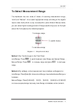
Page 19: ...the front panel as the following diagram To increase range To decrease range Diagram 2 1 Range Selection Keys Method 1 By Function keys on the Front Panel Auto Range Press to switch between Auto Rang...

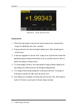
Page 20: ...so as to protect the instrument against damage and get exact data as much as possible when it s hard to predict the range of measurement 4 For Dual display Function the measurement ranges of Main dis...

Page 21: ...DCI ACI and 2 Wire 4 Wire Resistance Slow Middle and Fast 2 There is a linkage for both reading resolution and reading measurement rate 3 5 reading s belongs to 5 5 digit resolution 4 Both 20 reading...

Page 22: ...ital Multimeters have following basic functions To Measure DC Voltage To Measure AC Voltage To Measure DC Current To Measure AC Current To Measure 2 4 Wire Resistance To Measure Capacitance To Test Co...

Page 23: ...owing steps NOTE DC Voltage is always the selected function when the Multimeter is turned on Operating Steps 1 Press on the front panel to enter the DC Voltage measurement interface as shown in Diagra...

Page 24: ...the DC resistance as 10M default value or 10G Users can execute DC voltage measurement directly without modifying this parameter which has been setup before leaving factory 5 Set AC Filter function P...

Page 25: ...l be introduced in details as the following steps Operating Steps 1 Press and on the front panel to enter the DC Current measurement interface as shown in Diagram 2 6 Diagram 2 6 DC Voltage Measuremen...

Page 26: ...Set AC Filter function Press Filter to open or close the AC Filter 5 Set relative value Optional operation Press Rel to open or close Relative math function When it is opened the reading displayed is...

Page 27: ...ill be introduced in details as the following steps Operating Steps 1 Press on the front panel to enter the AC Voltage measurement interface as shown in Diagram 2 8 Diagram 2 8 AC Voltage Measurement...

Page 28: ...nput protection exists in every range 4 Set relative value Optional operation Press Rel to open or close Relative math function When it is opened the reading displayed is a relative value which comes...

Page 29: ...be introduced in details as the following steps Operating Steps 1 Press and on the front panel to enter the AC Current measurement interface as shown in Diagram 2 11 Diagram 2 11 AC Voltage Measuremen...

Page 30: ...are available for setting every range 4 Set relative value Optional operation Press Rel to open or close Relative math function When it is opened the reading displayed is a relative value which comes...

Page 31: ...stance will be introduced in details separately 2 Wire Resistance Operating Steps 1 Press on the front panel to enter the 2 Wire Resistance measurement interface as shown in Diagram 2 13 Diagram 2 13...

Page 32: ...tion Press Rel to open or close Relative math function When it is opened the reading displayed is a relative value which comes from the result of actual measurement value subtracts the value that has...

Page 33: ...panel to enter the 4 Wire Resistance measurement interface as shown in Diagram 2 14 Diagram 2 15 4 Wire Resistance Measurement Interface 2 Connect the red lead to terminal Input HI and black lead to t...

Page 34: ...al operation Press Rel to open or close Relative math function When it is open the reading displayed is a relative value which comes from the result of actual measurement value subtracts the value tha...

Page 35: ...ll be introduced in details as the following steps Operating Steps 1 Press on the front panel to enter the Capacitance measurement interface as shown in Diagram 2 16 Diagram 2 17 Capacitance Measureme...

Page 36: ...l to open or close Relative math function When it is opened the reading displayed is a relative value which comes from the result of actual measurement value subtracts the value that has been set Plea...

Page 37: ...quency or Period will be introduced in details as the following steps To Measure Frequency Operating Steps 1 Press and on the front panel to enter the Frequency measurement interface The lower right c...

Page 38: ...ss Rel to open or close Relative math function When it is opened the reading displayed is a relative value which comes from the result of actual measurement value subtracts the value that has been set...

Page 39: ...ram 2 21 Diagram 2 21 Period Measurement Interface 2 Connect the red lead to terminal Input HI and black lead to terminal Input LO as the following diagram Diagram 2 22 Sketch Map for Measuring Period...

Page 40: ...om the result of actual measurement value subtracts the value that has been set Please refer to Math Functions in Chapter 2 to know about the details 5 Read measurement result Period measurement is fi...

Page 41: ...ne it is considered being connected with instrument The method to test Continuity will be introduced in details as the following steps Operating Steps 1 Press on the front panel to enter the Continuit...

Page 42: ...A Ranges Fixed at 2k Open circuit Voltage 8V Input Protection 1000V on all ranges HI terminal Beep Condition 0 Rtesting Short circuit impedance 1 Short circuit impedance 2k 4 Set the Beeper function P...

Page 43: ...to test Diode will be introduced in details as the following steps Operating Steps 1 Press and on the front panel to enter the Diode test interface as shown in Diagram 2 25 Diagram 2 25 Diode Test In...

Page 44: ...rse the probes and measure the voltage in the diode once more Evaluate the diode according to the following rules If the Multimeter shows overload when in reverse bias model it indicates that the diod...

Page 45: ...rating Steps 1 Press on the front panel to enter the Temperature measurement interface as shown in Diagram 2 27 Diagram 2 27 Temperature Measurement Interface 2 Connect the red lead to terminal Input...

Page 46: ...ne to view the configuration as shown in the following diagram Diagram 2 30 Configuration of the Sensor 5 Press Display to choose a display mode The Multimeter supports three display modes Temperature...

Page 47: ...emperature And Voltage Values 6 Press Units to choose the unit of temperature The Multimeter supports three units C F K Diagram 2 33 Unit Selection Interface 7 Set relative value Optional operation Pr...

Page 48: ...hem to meet your own requirements AC Filter AC Filter is applicable for DC Voltage and DC Current measurement When DC Voltage or DC Current function is selected press Filter to open the filter as show...

Page 49: ...ce is general for the Multimeter but for 200mV and 2V manual ranges 10G should be chosen for better result The current selection will be saved in nonvolatile memory DC input impedance selection While...

Page 50: ...to enter interface as the following diagram Diagram 2 36 Set Up the Short circuit Resistance 2 Use direction keys to change the parameter values Press left and right directional keys to choose differ...

Page 51: ...ion Combinations shade is available Main Display Function DCV DCI ACV ACI FREQ PERIOD 2 Wire R 4 Wire R Cap Vice Display Function DCV DCI ACV ACI FREQ PERIOD 2 Wire R 4 Wire R Cap Explanations 1 If th...

Page 52: ...tatistics Limits Relative is used in Main Display when opening Vice Display the result will still be shown in Main Display and Vice Display will show the second selected function normally 3 If Tempera...

Page 53: ...n as the following diagram shows Diagram 2 37 Utility Function Configuration Interface Table 2 13 Utility Function Menu Description Function Menu Description Store Recall Store or recall setting files...

Page 54: ...eters and data files in the local storage as well as in USB storage Operating Steps 1 After entering into the function menu of Utility press Store Recall to enter the interface as shown in diagram 2 3...

Page 55: ...o enter the following interface Use direction keys to choose storage path and location and press Select to recall the corresponding file Diagram 2 40 Recall Function Interface 4 Press Power on to set...

Page 56: ...as well as in USB storage Operating Steps 1 After entering into the function menu of Utility press Manage File to enter the interface as shown in diagram 2 41 Diagram 2 41 Manage File Interface 2 Choo...

Page 57: ...Press Done to save the current file and return to the higher level menu Press Cancel to cancel the current operation and return to the higher level menu 4 Press Action and select Folder Capture Displa...

Page 58: ...Settings The Multimeter enables users to operate instrument remotely by LAN interface and store or recall internet settings You can look over current LAN settings and set up IP address and subnet mas...

Page 59: ...Settings Only for SDM3055A Each device on the GPIB IEEE 488 interface must have a unique address The default address is 30 when the instrument is leaving the factory The address of Multimeter can be a...

Page 60: ...Test Function Description Function Menu Description Key Test the instrument s keys LCD Test the instrument s LCD screen Beeper Test the instrument s beeper Chip Test the instrument s chips Done Retur...

Page 61: ...t the test and observe if the screen has severe color or other display error As the Diagram 2 48 shows Diagram 2 48 LCD Test Interface NOTE Before you operate the shapes on the screen display blue col...

Page 62: ...er one time and the instrument will beep one time 5 Test the chips Press Chip Start to enter chip test interface as Diagram 2 49 shows Diagram 2 49 Chip Test Interface 6 Press Done to exit the board t...

Page 63: ...t the update file Next press Update Yes to start updating the system software 4 After accomplishing update the screen shows message Firmware Update Done Then you can move the USB flash drive away 5 Re...

Page 64: ...tings Menu Description Function Menu Description Language Select the display interface language Screen Set up the screen protection function System Info View system information Done Return to the high...

Page 65: ...rent demands Activate the screen saver program and screen saver will be on if no action is taken within the time that you have selected Press any button the resume 3 View system information Press Syst...

Page 66: ...r Press to enter the interface shown as the following diagram Diagram 2 52 Acquire Interface Table 2 19 Function Menu of triggering parameter Function Menu Description Trg Src Set the source of trigge...

Page 67: ...Left and Right keys are used to switch the number of a numerical value Up and Down keys are used to change the selected value 3 Set the number of samples or trigger Press Samples Trigger to set the sa...

Page 68: ...then select Trg Src Single or press on the front panel directly to enable Single Trigger See the diagram below Diagram 2 53 Setting interface of Auto Trigger 2 Set the delay Press Delay to select Auto...

Page 69: ...ss on the front panel directly to enable External Trigger Diagram 2 54 Setting interface of Ext Trigger 2 Set the polarity of slope Press Slope to choose Positive or Negative polarity 3 Set the delay...

Page 70: ...erations with the help list Press and to enter the help list as the following diagram shows Diagram 2 55 Help Menu Table 2 20 Help System Operating Menu Function Menu Description Up Move up the cursor...

Page 71: ...he data parameter sensors files 7 Optional Multiple Scan Card Get help about operating optional multiple scan cards 8 The convention and Tips of Softkeys Get help about the convention and tips of soft...

Page 72: ...functions can only be used in DC Voltage AC Voltage DC Current AC Current Resistance Frequency Period and Temperature measurement Among these functions dBm and dB are only used in DC Voltage and AC Vo...

Page 73: ...specified upper and lower limits dBm The dBm is based on a calculation of power delivered to a reference resistance 0dBm 1mW dB The dB measurement is the difference between the input signal and a stor...

Page 74: ...22 Statistic Measurement Menu Function Description Function Menu Settings Description Statistics Show Hide Show or hide the statistics function interface Min Show the minimum statistics value of curr...

Page 75: ...nction the first reading is usually set to the maximum or minimum value When getting more readings current displaying value is always the maximum minimum reading among all the measured values The maxi...

Page 76: ...t Menu Function Description Function Menu Settings Description Limits On Off Turn on or turn off the Limits function Low Set the desired lower limit Center Set the desired center value High Set the de...

Page 77: ...limit the color of main display will switch blue to red When the reading is higher than the set higher limit the color of main display will switch blue to red When the reading is lower or higher than...

Page 78: ...m Function Interface Table 2 24 dB Measurement Function Menu Function Description Function Menu Settings Description dB dBm On Off Turn on or turn off dB or dBm function Function dBm Open dBm function...

Page 79: ...or dBm function Function dB Open dB function and the lower right corner of the main display show dB Ref R Set the parameter via direction keys 50 8000 dB Ref Value Set the referred value of dB Measure...

Page 80: ...esistance Frequency Period Capacitance and Temperature Press Rel Value to enter the interface shown in the following diagram Diagram 2 62 Relative Operation Table 2 26 Rel Value Operation Function Men...

Page 81: ...types of way to view measured data Number Bar Meter Trend Chart and Histogram Number Press and to open the menu of display mode and press Display to enter the following interface Number is always the...

Page 82: ...oose the way to set the vertical scale as Default or Manual mode Table 2 27 To Set the Vertical Scale of Bar Meter manually Function Menu Description Low Set the low value of horizontal scale High Set...

Page 83: ...ription Display Trend Currently selected display mode is Trend Chart Recent All Show recent or all readings Horizontal Scale Choose the mode of Horizontal Scale Autoscale Once Automatically set the ho...

Page 84: ...SIGLENT 74 SDM3055 Digital Multimeter Press Manual and you can set the vertical scale manually as the following diagram shows Diagram 2 67 Manual Vertical Scale...

Page 85: ...Histogram Currently selected display mode is Histogram Binning Set Binning as Auto or Manual mode Bin Set Set the parameters of Bin Cumulative On Off Turn on or off Cumulative function Clear Readings...

Page 86: ...ns 10 20 40 100 200 or 400 selected Low Set the low value of horizontal scale High Set the high value of horizontal scale Center Set the center value of horizontal scale Span Set the span of horizonta...

Page 87: ...ure continuous readings automatically By the time the black field of the screen will show Auto Trigger Press again and the trigger is stopped Single Trigger Press on the front panel Single Trigger wil...

Page 88: ...n view measured history data Press and to open Hold measurement function interface the black field just above the screen will show Probe Hold as shown in the following diagram Diagram 2 70 Hold Measur...

Page 89: ...users control and manipulate SDM3055 quickly Example 1 Reading Statistic Functions Example 2 To Eliminate Leads Impedance Example 3 dBm Measurement Example 4 dB Measurement Example 5 Limits Test Exam...

Page 90: ...ront panel to select AC Voltage measurement function and choose a proper voltage range 2 Connect the red lead to terminal Input HI and black lead to terminal Input LO as Diagram 2 9 3 Set the Statisti...

Page 91: ...ent function 2 Connect the red lead to terminal Input HI and black lead to terminal Input LO as Diagram 2 14 3 Choose a proper resistance range according to the scope The default is Auto Range 4 Lead...

Page 92: ...SIGLENT 82 SDM3055 Digital Multimeter 6 Besides pressing Rel on the softkey menu could also open Relative operation The Relative Operation has been turned on Diagram 3 5 Lead Impedance after Operation...

Page 93: ...the red lead to terminal Input HI and black lead to terminal Input LO as Diagram 2 9 3 Set the dBm parameters Press Statistics to turn on the statistics function and set the selective value of dBm as...

Page 94: ...ng Steps Method 1 Measure dBm1 and dBm2 existing in two circuits separately according to Example 3 and then dB could be got dB dBm1 dBm2 Method 2 1 Press on the front panel to select AC Voltage measur...

Page 95: ...ENT SDM3055 Digital Multimeter 85 5 Press Done to return to the higher level menu At this time the reading shown on the screen is the power difference between two circuits Diagram 3 9 dB Operation Res...

Page 96: ...sound is on Operating Steps 1 Press on the front panel to select AC Voltage measurement function and choose a proper voltage range 2 Connect the red lead to terminal Input HI and black lead to termin...

Page 97: ...between the Low and High limits so the test status is True 5 If changing the high limit value to 1V the measured result is not between the Low and High limits So the instrument beep once and the main...

Page 98: ...te temperature of hot side Besides only the relationship between thermocouple voltage and cold side temperature is need to be input according thermocouple type when you set the thermocouple sensor Ope...

Page 99: ...ng file and press Read to recall the sensor settings file Diagram 3 15 Select Sensor Settings File 4 Press Units to choose the unit of temperature 5 View measured result Press Display and select displ...

Page 100: ...nd choose a proper voltage range 2 Connect the red lead to terminal Input HI and black lead to terminal Input LO as Diagram 2 4 3 Press and to open Hold measurement function interface By the time the...

Page 101: ...SIGLENT SDM3055 Digital Multimeter 91 Diagram 3 18 Result 2...

Page 102: ...as the following steps Operating Steps 1 Connect the Multimeter to your computer by using USB data wire 2 Open the main interface of EasySDM Click Control on the upper left corner and choose Connect t...

Page 103: ...are waves the AC and AC DC values are equal since these waveforms do not contain a DC offset See the following table 5 1 Table 5 1 True RMS AC Measurement of Sine Triangle and Square waves Waveform Cr...

Page 104: ...ction of chapter 6 The crest factor errors do not apply for input signals below 100Hz You can estimate the measurement error due to signal crest factor as shown below Total Error Error Sine wave Error...

Page 105: ...so add additional capacitance and loading The approximate input resistances of the Multimeter at different frequencies are listed in the following table Table 5 2 Approximate Input Resistances at Diff...

Page 106: ...er reading offset The Multimeter should be cleared under the selected range and reading rate to decrease the offset when using the analog filter If you cannot clear the instrument the measured results...

Page 107: ...O jack correctly 2 Check if the fuse in the current location on the back panel has blown 3 Check if the measuring location has switched to the DCI or ACI place correctly 4 Check if the input is ACI bu...

Page 108: ...ination country Two test leads black and red An USB Cable One backup fuses A Quick Start An Application software NOTE We suggest that the length of USB data wire and LAN cable connected to the instrum...

Page 109: ...LENT will provide repair or replacement as described in the complete warranty statement To arrange for service or obtain a copy of the complete warranty statement please contact your nearest SIGLENT s...

Page 110: ...e external ash of the instrument and probe by a soft rag Be careful not to scratch the transparent plastic protective screen when cleaning the liquid crystal screen Use a soft rag that has been soaked...

Page 111: ...ct SIGLENT SIGLENT TECHNOLOGIES CO LTD Address 3F NO 4 building Antongda Industrial Zone 3rd Liuxian Road 68th District Baoan District Shenzhen P R China Tel 86 755 36615186 Fax 86 755 3591582 Post Co...

Reviews: