EAN-4000-OEM-MIPI-Cameras
© SightLine Applications, Inc.
2
Power and network connectivity LEDs:
A green light (D1) on the 4000-OEM board indicates that all boards are powered on. An amber light
(D5) verifies network connection.
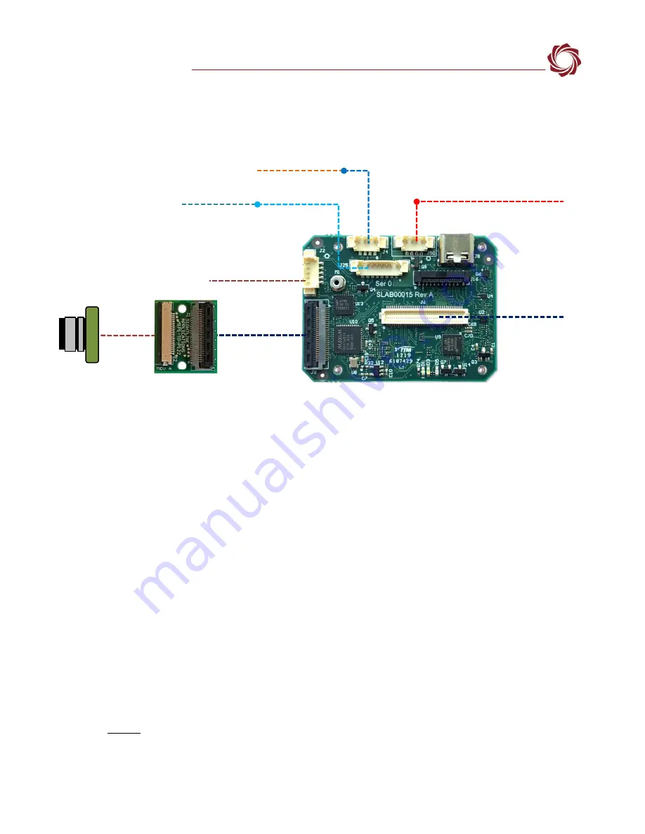
Figure 1: 4000-OEM MIPI Camera Bench Setup
4
Configuration Settings
This section covers the basic camera configuration settings in Panel Plus for the SightLine 4000-OEM
video processing board.
Before connecting with the Panel Plus software, the OEM board should be powered up and connected
through:
-
a network switch or directly to the host PC (preferred) or,
-
Direct serial connection (for troubleshooting or if a network connection cannot be established).
See the
for connection and video streaming instructions.
IMPORTANT:
This procedure assumes that the customer has read the OEM startup guide(s) and
has a basic understanding of the following fundamentals:
•
Completed a functional connection between the SightLine video processing board and Panel
Plus application
•
Familiar with Panel Plus controls
•
Successfully streamed video in Panel Plus
If you do not have a strong basic system setup and familiarity, we recommend reviewing the OEM
startup guide and work with our support team to establish basic connection and streaming
fundamentals.
Network Switch or PC Direct
SLA-CAB-1504 (J50)
Serial (SLA-CAB-504)
SLA-CAB-0403 (J4)
4000-OEM
RJ45 Ethernet
SLA-PWR-B12V-36W
Optional Serial SLA-CAB-0305
USB to PC
SLA-CAB-0804
SLA-CAB-MIPI-02 (J9)
MIPI
Camera
The camera is immediately
powered on when power is
connected to the OEM board.
(J6)
Optional Camera
Adapter Boards
MIPI Camera
Cable
4000-P122 Board


