


Hardware Design Guide
Rev 3.0 Aug.19
20
41111116
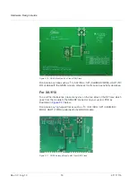
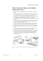
Figure 2-21: Example of Bad GPS Module Placement (Patch Antenna Close to a High-Profile Metal
Case Component) and Good Placement
Placement
•
Place the decoupling capacitors for the
VCC
close to the GNSS module.
•
Place the damping resistors for
TX/RX
close to GNSS module.
Do not place the GNSS module:
•
in proximity to high-speed digital processing circuitry
•
in proximity to high-current switching power circuitry
•
in proximity to clock sources circuitry
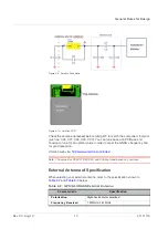
Trace
1.
The USB differential signals should be traced closely and be of equal length
for better noise immunity and minimum radiation.
2.
Apply a 50 ohm impedance RF trace for correct impedance matching.
3.
Any right angle turn in trace routing should be done with two 135 degree
turns or an arc turn.
Figure 2-22: Examples of turns in trace routing
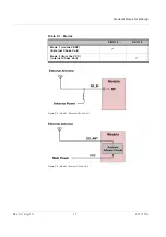
It is better to have an independent trace of the power source for all components: