Bus Detection
Loop Detector Application Notes SLD4
667/HQ/45200/101
14
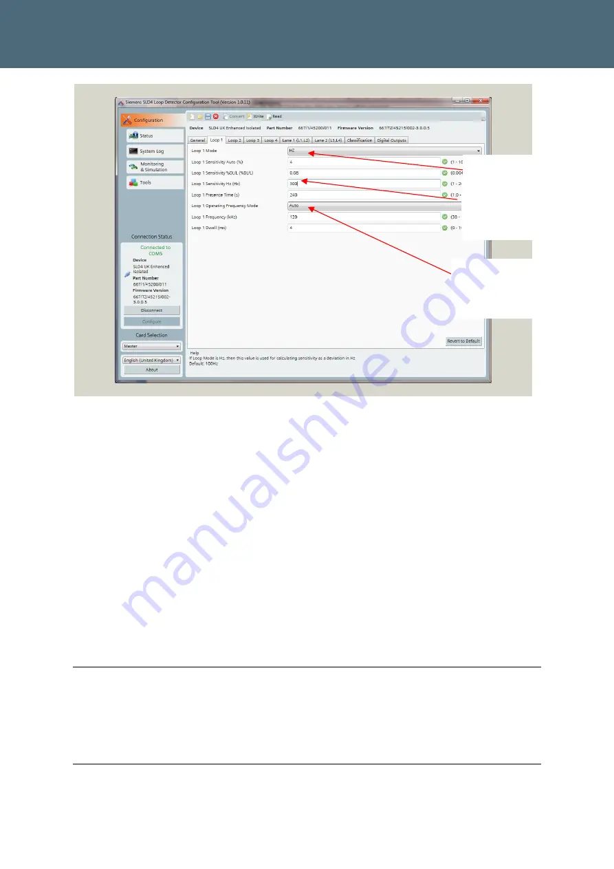
Figure 4 : Setting Loop Mode
6
Click on Monitoring and Simulation tab to assess the required sensitivity.
7
Click on Capture vehicles button to start the real-time vehicle data capture. The tool will
capture vehicles in real time. You need to check the maximum deviation in frequency for
the target vehicles.
8
Once you have completed the Vehicle Capture click on the End Capture Button. You can
now save this data for future reference if required by clicking on the Disc icon.
9
Click on the Configuration tab. The profiles will vary but it is important, to set the sensitivity
such that all target vehicles are captured. You will find that other vehicles (Cars, Vans etc)
will have a lower deviation should be set to a sensitivity value, 20% less than the deviation
for the target vehicles. In the example shown below, the sensitivity will be set to 1200Hz
and then the Write Button clicked, set up is now complete but can be adjusted at any time
by using the Configurator tool. A threshold of 1200Hz falls mid-way between the devia-
tions for buses and for cars/vans (typically 400Hz).
Note
The “Loop sensitivity Hz (Hz)” should be left at the default (20) until the loop sensitivity has
been assessed using the Monitoring and simulation page, details of which are shown in Figure
5
Note (9) Typical values assume there is no Rebar, Buried metal or Slag waste present, which
will alter the frequency variations mentioned above (especially in the North East of the UK.
Set Loop Mode to Hz
Leave in Default (Auto)
Loop sensitivity to be set
once the optimum has
been assessed


