


To INCREASE the Digital Damping:
1. Press the <1> key while viewing the Test Facilities Graph Screen as shown above. The
damping control [MinDamp #] will appear on the command line at the lower left-hand corner
of the screen.
Note
The number listed to the right of the command code on the screen represents the exponent
in the exponential averaging routine (digital damping), where the larger the number
represents the greater the digital averaging. Setting this exponent higher than 7 is
generally not recommended.
2. Pressing the <+> key will increase the MinDamp Factor by one unit for each key press. To
exit this mode, press the <0> key on the keypad.
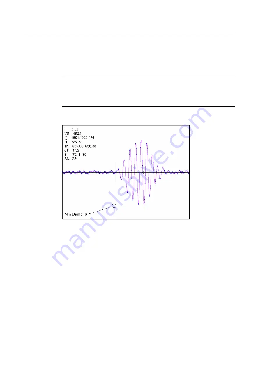
①
Increased Damping Factor
Figure 10-3 Setting the MinDamp Factor
The above example shows that increasing the Digital Damping reduces asynchronous noise.
Setting the Digital Damping factor to a value LOWER than the default value of 4 may be justified
in cases where pulsating flow is present (such as from a reciprocating pump) or for the purpose
of diagnosing transient signal behavior. A pulsating flow condition that generates more than
+/- 45 degrees of phase jitter will generally cause signal correlation problems when any digital
averaging is used. In this case it may be necessary to completely eliminate the digital averaging
by reducing the Digital Damping Factor to 0.
To DECREASE the Digital Damping:
1. Press the <2> key while viewing the Test Facilities Graph Screen. The damping control
[MaxDamp #] will appear on the command line at the lower left-hand corner of the screen.
2. Pressing the <-> key will decrease the MaxDamp Factor by one unit for each key press.
To exit this mode, press the <0> key on the keypad.
Troubleshooting
10.3 Test Facilities Graph Screen
FUP1010 IP67 Portable Flowmeter
124
Operating Instructions, 02/2010, A5E02951522A Revision 01
Summary of Contents for SITRANS FUP1010
Page 2: ......
Page 66: ......
Page 136: ......
Page 138: ......
Page 150: ......
Page 153: ...1010WP 7 21614 C ...
Page 154: ...1010WP 7 21614 C ...
Page 155: ...1010WDP 7 21614 C ...
Page 156: ...1010WDP 7 21614 C ...
Page 157: ...1010WP 8 21614 C ...
Page 158: ...1010WDP 8 21614 C ...
Page 159: ......
Page 161: ...1012FP 8 DIRECT MODE REFLECT MODE INSTALLED ON PIPE 21614 C ...
Page 162: ...1011PPS 8 TRANSDUCER PART NUMBER L H W NET WT PAIR X Z 21614 C SIZES A B C D SIZE E ...
Page 163: ...21614 C ...
Page 164: ......
Page 165: ......
Page 166: ......
Page 167: ......
Page 168: ...21614 C ...
Page 169: ...21614 C ...
Page 170: ...21614 C ...
Page 171: ...21614 C ...
Page 172: ...21614 C ...
Page 173: ...21614 C ...
Page 174: ...21614 C ...
Page 175: ...1015BC 1W 8 21614 C ...
Page 176: ......
Page 177: ...21614 C ...
Page 178: ...21614 C ...
Page 179: ...1012TP S 8 OUTLINE DIMENSIONS REFLECT MODE DIRECT MODE 1012TP S SERIES 21614 C MOUNTING TRACK ...
Page 180: ...REFLECT MODE DIRECT MODE 21614 C ...
Page 181: ...21614 C ...
Page 182: ...1015BC 1 8 21614 C ...
Page 183: ...21614 C INPUT OUTPUT TERMINALS 1015WP T10 8 ...
Page 184: ...21614 C INPUT OUTPUT TERMINALS 1015WP T26 8 ...
Page 185: ......
Page 186: ......
Page 187: ......
Page 188: ......
Page 190: ...DUAL HEAD CONFIGURATION 21614 C IN LINE CONFIGURATION FLOW ...
Page 191: ......
Page 192: ......
Page 194: ......
Page 204: ......
Page 206: ......
Page 207: ......